Choosing Fence Gates for Security, Pool, and High-Wind Scenarios
Learn how to match fence gates to specific property scenarios. Discover hardware specs, code compliance, and wind-load frameworks for lasting installations.
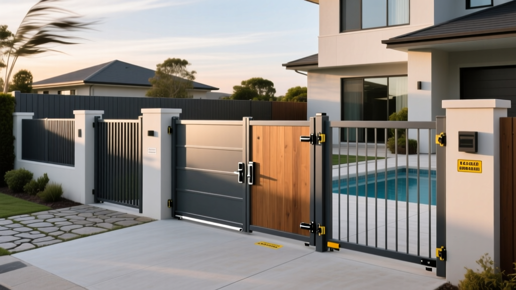
The Physics of Gate Sag and Scenario Mismatch
Up to 70% of premature fence gate failures stem from a fundamental mismatch between the gate's structural profile and its specific environmental or operational scenario. A gate is not merely a swinging panel; it is a dynamic cantilevered structure. When a standard 4-foot by 6-foot wood gate weighing 130 pounds is hung on a 4x4 wooden post using standard 4-inch butt hinges, the moment of force exerted on the top hinge exceeds 250 pounds of pull-out tension. Over time, seasonal moisture expansion, wind shear, and daily kinetic vibration cause the hinge post to deflect, resulting in irreversible gate sag.
Matching fence gates to their precise application requires moving beyond aesthetic choices and engineering the installation around specific stressors: lateral wind loads, high-frequency automation cycles, strict municipal safety codes, or forced-entry resistance. This guide provides exact material specifications, hardware sizing, and code-compliance frameworks for the most demanding property scenarios.
Scenario Matrix: Matching Gate Profiles to Site Conditions
Use the following decision matrix to identify the baseline structural requirements for your specific property scenario before selecting materials.
| Primary Scenario | Recommended Framing Material | Optimal Hinge Hardware | Minimum Post Specification | Critical Success Factor |
|---|---|---|---|---|
| High-Wind / Coastal | 14-Ga Galvanized Steel Tubing | 5/8' Thru-Bolted Strap Hinges | 6x6 Steel or 8x8 Treated Wood | Picket spacing to reduce sail effect |
| Pool / Spa Enclosure | Aluminum or Powder-Coated Steel | Self-Closing Tension Hinges | 4x4 Aluminum (Mortar Set) | BOCA/IRC 54-inch latch compliance |
| High-Security Perimeter | 9-Ga Welded Wire / Steel Tube | Heavy-Duty Weld-On Pivot Hinges | 8x8 Steel (Concrete Encased) | Anti-climb geometry and 3-point locks |
| Automated Driveway | Aluminum Frame with Steel Core | Sealed Ball-Bearing Roller Hinges | Masonry Pillar or 10x10 Steel | Weight distribution and motor sizing |
Deep Dive: High-Wind and Coastal Installations
In regions subject to ASCE 7-22 wind load standards, a solid 6-foot privacy gate acts as a massive sail. During a 90 mph gust, a solid-surface gate experiences over 150 pounds of lateral sheer force per linear foot. Standard wood framing will bow, and nails will sheer under cyclic wind loading.
Hardware and Framing Specifications
For high-wind scenarios, abandon traditional 2x4 wood framing. Instead, construct the gate frame using 2x3-inch 14-gauge galvanized steel tubing, joined with continuous MIG welds or structural corner gussets. If wood pickets are required for aesthetics, attach them using 1/4-inch stainless steel lag screws rather than nails.
For the hinge post, use a 6x6-inch steel post set 36 inches deep in 3,500 PSI concrete. Attach the gate using heavy-duty strap hinges secured with 5/8-inch thru-bolts and nylon-insert lock nuts. The strap hinges distribute the kinetic load across a 24-inch vertical span of the gate frame, preventing the localized tearing that occurs with standard butt hinges.
Deep Dive: Pool Safety and BOCA Code Compliance
Pool enclosure gates are governed by strict liability and life-safety codes. The International Residential Code (IRC) Section R326 and the legacy BOCA guidelines mandate specific mechanical behaviors to prevent unsupervised toddler access. Failing to match your gate hardware to these codes can result in failed municipal inspections and severe civil liability.
The 54-Inch Rule and Latch Mechanics
The most critical specification for pool fence gates is the latch release mechanism. Codes universally require that the latch release be located on the pool-side of the gate and positioned at least 54 inches above the bottom of the gate. If the latch is lower than 54 inches, there must be no horizontal cross-rails or decorative cutouts within 18 inches of the latch that a child could use as a foothold to reach over and release it.
'Residential pool barriers must feature self-closing and self-latching gates. The latch must require a deliberate release action and automatically engage when the gate swings shut from a 90-degree open position.' — Consumer Product Safety Commission (CPSC) Safety Barrier Guidelines.
Actionable Hardware Selection: Equip pool gates with the D&D MagnaLatch TL3. This specific model utilizes magnetic and gravity mechanics to ensure positive latching every time, eliminating the mechanical spring fatigue common in standard gravity latches. Pair this with Locinox TruClose self-closing hinges, which allow for precise tension adjustment via a hex key without removing the gate from the post. Ensure the gate swings outward, away from the pool area, so that a child pushing against it will only force it tighter into the latch.
Deep Dive: High-Security and Perimeter Control
Commercial properties, utility substations, and high-value residential estates require gates designed to defeat climbing, cutting, and vehicular ramming. The American Fence Association outlines strict parameters for perimeter security that go far beyond standard residential chain-link.
Anti-Climb Geometry and Crash Ratings
For anti-climb applications, specify 9-gauge welded wire mesh with a 2x2-inch or smaller aperture (such as 358 Prison Mesh). The small aperture prevents fingers and bolt cutters from gaining purchase. The gate frame must be constructed from 3-inch square steel tubing with a minimum wall thickness of 0.188 inches.
If the scenario involves protection against vehicular ramming (e.g., guard shacks or data centers), the gate must be tested to ASTM F2656 crash ratings. An M50-P1 rating indicates the gate can stop a 15,000-pound truck traveling at 50 mph with less than 1 meter of dynamic penetration. These gates require massive 12-inch steel beam frameworks and deep-foundation hydraulic operators, entirely precluding DIY or standard residential fencing contractors.
For standard high-security pedestrian gates, utilize a 3-point locking mechanism. This involves a primary mortise lock combined with top and bottom shoot-bolts that penetrate the header and concrete threshold, preventing the gate from being pried open with a crowbar.
Automated Driveway Entry: Swing vs. Slide Decision Tree
Automating a gate introduces continuous kinetic stress. Choosing the wrong gate type for the terrain or snow-load scenario will burn out operators within a single season.
- Choose Dual-Swing Gates If: The driveway is perfectly level, space behind the gate is clear of snow accumulation or vehicle bumpers, and you want a lower initial hardware cost. Use articulated arm operators (e.g., LiftMaster RSL-12UL for commercial or Ghost Controls PRO for residential). Limitation: Swing gates fail in heavy snow regions where snowbanks block the swing arc.
- Choose V-Track Sliding Gates If: The driveway is level but space is limited, and you need high wind resistance. The gate rolls on a steel V-track welded to the bottom rail. Limitation: V-tracks clog with ice, gravel, and debris, causing motor stall-outs.
- Choose Cantilever Sliding Gates If: The terrain is sloped, or the region experiences heavy snow and ice. Cantilever gates roll on sealed carriage bearings mounted to the posts, keeping the gate elevated 2 inches above the ground. This is the only viable automated option for commercial sites in northern climates.
Hardware Weight Capacity and Sizing Chart
Undersizing hinges is the most common installation error. Use this chart to match hinge types to gate weight profiles.
| Gate Weight Class | Typical Dimensions / Material | Required Hinge Type | Minimum Hinge Load Rating (Per Pair) |
|---|---|---|---|
| Light Duty (Under 100 lbs) | 3x5 ft Aluminum / Vinyl | Standard Self-Closing Polymer | 150 lbs |
| Medium Duty (100 - 250 lbs) | 4x6 ft Wood / Wrought Iron | Heavy-Duty Strap or Ball-Bearing | 400 lbs |
| Heavy Duty (250 - 600 lbs) | 6x8 ft Solid Wood / Steel Frame | 5/8' Thru-Bolted Steel Strap | 800 lbs |
| Industrial (600+ lbs) | Automated Driveway / Cantilever | Weld-On Thrust Bearing Pivot | 1,500+ lbs |
Troubleshooting Premature Hardware Fatigue
Even with the correct scenario matching, gates fail if installation tolerances are ignored. Address these specific failure modes during installation:
1. The 'Hinge-Bind' Effect: If a gate is hung perfectly plumb but the hinge post deflects even 1/4 inch under the gate's weight, the top and bottom hinges will fight each other, creating immense friction. Fix: Install the gate with a 1/8-inch intentional 'lean' toward the latch side, or use adjustable tension hinges that allow for micro-alignment post-installation.
2. Concrete Spalling on Post Bases: Setting steel gate posts directly into concrete without a gravel drainage base traps water inside the post. Freeze-thaw cycles will spall the concrete and rust the post from the inside out. Fix: Place 2 inches of crushed gravel at the bottom of the post hole, and slope the concrete collar away from the post at a 5-degree angle to shed surface water.
3. Automation Limit-Switch Drift: Automated gates that slam into the latch post or fail to close fully usually suffer from thermal expansion altering the physical travel distance. Fix: Do not rely on physical limit switches for heavy steel gates. Specify operators with absolute encoders or current-sensing technology that maps the gate's travel profile dynamically, adjusting for temperature-induced friction changes.