Technical Specifications for Applying Stone Veneer for Retaining Wall Structures
Engineering guidelines and technical specifications for installing stone veneer for retaining wall applications, covering substrate, drainage, and mortar.

Core Engineering Premise: Veneer is Non-Structural
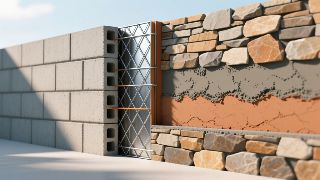
When specifying stone veneer for retaining wall applications, the fundamental engineering constraint is that the veneer itself provides zero structural resistance to lateral earth pressure. The veneer is purely an architectural cladding. The structural retaining wall behind it—typically reinforced Concrete Masonry Units (CMU) or poured concrete—must independently satisfy all geotechnical load requirements, including surcharge loads, hydrostatic pressure, and seismic forces. Applying veneer to a retaining wall introduces new failure vectors, primarily shear delamination and moisture entrapment, which must be mitigated through strict adherence to material specifications and drainage integration.
Structural Substrate Requirements
The substrate must be rigid, dimensionally stable, and capable of supporting the dead load of the stone veneer (which typically ranges from 10 to 15 pounds per square foot) without excessive deflection. The maximum allowable deflection for the substrate under full lateral load is L/600.
Concrete Masonry Unit (CMU) Specifications
- Unit Size: Minimum 8-inch nominal thickness.
- Compressive Strength: Minimum 3,750 psi net area compressive strength per ASTM C90.
- Reinforcement: Vertical #4 (1/2-inch) Grade 60 rebar spaced at 48 inches on center (O.C.), extending from the footing into the wall. Horizontal #4 joint reinforcement every 16 inches O.C.
- Grouting: All cells containing rebar must be grouted solid with minimum 2,000 psi grout (ASTM C476).
Poured Concrete Specifications
Cast-in-place concrete walls must achieve a minimum 28-day compressive strength of 3,000 psi (ASTM C39). The surface must be left with an open-pore, coarse broom finish to ensure mechanical keying for the scratch coat. Form release agents containing waxes or silicones are strictly prohibited, as they act as bond-breakers for the masonry mortar.
Moisture Management and Hydrostatic Drainage
Retaining walls are inherently exposed to massive hydrostatic pressure. If water becomes trapped between the structural wall and the stone veneer, freeze-thaw expansion will generate outward pressures exceeding 100,000 pounds per square foot, leading to catastrophic veneer blowout. Moisture management requires a dual-drainage approach.
Primary Drainage (Behind the Structural Wall)
A 4-inch perforated PVC pipe (ASTM D2729) must be installed at the base of the structural wall, wrapped in a non-woven geotextile fabric (minimum 4 oz/sq yd) to prevent soil migration. The backfill must consist of clean, washed 3/4-inch crushed stone extending 12 inches behind the wall.
Secondary Drainage (Through the Veneer)
According to the Brick Industry Association Technical Notes on Weep Holes, any adhered masonry veneer on a retaining structure must feature weep holes to allow incidental moisture that penetrates the veneer to escape.
- Weep Hole Diameter: Minimum 3/8-inch PVC tubing.
- Spacing: 32 inches O.C. along the base course of the veneer, immediately above the finished grade or hardscape.
- Flashing: A continuous through-wall flashing (minimum 40-mil PVC or rubberized asphalt) must be installed at the base of the veneer, lapping up the structural wall by a minimum of 8 inches and extending through the veneer mortar joint to daylight.
Adhesion Matrix: Mortar, Lath, and Anchoring
The bond between the stone veneer and the structural substrate is the most critical point of failure. The adhesion system must resist both the dead load shear force and the tensile forces generated by thermal expansion and contraction.
| Component | Specification Standard | Technical Requirement |
|---|---|---|
| Metal Lath | ASTM C847 | 2.5 lb/sq yd self-furring galvanized steel. Attached with 1.5-inch galvanized concrete nails at 6-inch O.C. staggered. |
| Scratch Coat | ASTM C926 | 1/2-inch to 3/4-inch thickness. Must fully encapsulate the lath. Scored horizontally with a coarse rake to provide a mechanical key. |
| Setting Mortar | ASTM C270 Type S | 1 part Portland cement, 1/2 part hydrated lime, 4.5 parts damp loose sand. Minimum 1,800 psi compressive strength. |
| Polymer Adhesive | ANSI A118.4 | Modified dry-set mortar for high-shear applications. Used only for manufactured stone veneer under 10 lbs/sq ft. |
For natural stone veneer exceeding 12 inches in vertical height or weighing more than 12 lbs/sq ft, mechanical anchoring is required in addition to mortar adhesion. Corrosion-resistant masonry ties (ASTM A153 Class B-2 galvanized) must be embedded into the structural substrate and hooked into the mortar joints of the veneer at a rate of one tie per 3.5 square feet of wall area. The National Concrete Masonry Association (NCMA) emphasizes that mechanical ties are non-negotiable for heavy natural stone cladding on civil structures subject to vibration or heavy surcharge loads.
Freeze-Thaw Dynamics and Coping Details
The top of a retaining wall is highly vulnerable to water ingress. If water enters the top of the wall, it migrates down the back of the veneer, saturating the scratch coat. When temperatures drop, the freezing water expands by 9%, spalling the stone and destroying the mortar bond.
Technical Coping Requirements
- Overhang: The structural coping or capstone must overhang the stone veneer face by a minimum of 1.5 inches.
- Drip Edge: A 3/8-inch deep drip kerf must be cut into the underside of the coping overhang, exactly 1/2 inch from the face, to force water droplets to detach and fall clear of the veneer.
- Sealant: The joint between the coping and the structural wall must be sealed with a high-modulus, non-sag polyurethane sealant compliant with ASTM C920 (Type S, Grade NS, Class 25). Silicone sealants are prohibited due to poor adhesion to masonry dust and mortar.
Forensic Analysis: Common Failure Modes
When stone veneer for retaining wall projects fails, it is almost always traceable to specific deviations from the specifications outlined above. Understanding these failure modes allows engineers and contractors to preemptively address edge cases during construction.
Symptom: White, powdery salt deposits build up behind the veneer, eventually pushing the stone off the wall.
Root Cause: Soluble salts in the backfill soil or CMU blocks are dissolved by water and migrate through the porous concrete. The water evaporates at the veneer mortar joint, leaving crystallized salts that expand and fracture the joint.
Technical Fix: Apply a silane/siloxane penetrating water repellent to the back face of the structural wall before installing the lath. Ensure backfill drainage stone is washed and free of fine clay particles.
Symptom: The bottom three courses of stone veneer detach from the wall and slide outward, while the upper courses remain intact.
Root Cause: The cumulative dead load of the veneer exceeds the shear bond strength of the mortar at the base, often exacerbated by soil settlement pushing against the base course.
Technical Fix: Install a continuous galvanized steel angle iron (minimum 3x3x1/4 inch) anchored directly into the concrete footing with 1/2-inch wedge anchors spaced every 16 inches. The base course of stone must rest entirely on this steel shelf, transferring the dead load directly to the footing rather than relying on mortar adhesion.
Expansion Joint Spacing
Retaining walls expand and contract with seasonal temperature shifts. The stone veneer must not bridge structural expansion joints. Vertical expansion joints in the veneer must align exactly with the expansion joints in the structural CMU or poured concrete wall behind it. These joints should be a minimum of 3/8-inch wide and filled with closed-cell polyethylene backer rod and ASTM C920 polyurethane sealant. Failing to align these joints will result in concentrated stress fractures running diagonally through the stone veneer at the exact location of the structural joint.
Written by
Priya KapoorPriya Kapoor is a real estate market analyst and construction economics researcher with expertise in housing affordability, development feasibility, and infrastructure investment. She holds a Master of Regional Planning from Cornell University and previously worked as a senior analyst at CBRE's Investment Properties group, where she modeled returns for $4B in mixed-use development pipelines. Priya now runs an independent research practice advising developers, municipalities, and REITs on construction cost forecasting and market timing. She publishes the quarterly "BuildMat Market Pulse" report tracking material price indices across 12 commodity categories. Based in Austin, TX, Priya serves on the board of Habitat for Humanity Austin and is a marathon runner.
More from Priya Kapoor
View all
Construction Cost
Cost to Build a 1600 Sq Ft Home in 2026: Full Breakdown
Accurate 2026 cost to build a 1600 sq ft home—material, labor, and regional pricing breakdowns included. Plan your budget with real-time estimates.
Aug 11, 2026
Wood & Lumber
Name the Types of Wood for Pressure Treatment and Preservation
Learn how to name the types of wood best suited for pressure treatment. Compare species treatability, chemical retention levels, and 2026 preservation costs.
Aug 4, 2026
Stone & Masonry
Stone Veneer Suppliers Lindenhurst: 2026 Cost Analysis
Analyze 2026 stone veneer costs in Lindenhurst, NY. Compare local supplier pricing, delivery fees, and Suffolk County installation labor rates.
Aug 4, 2026