Flashing Roof Performance: ASTM Specs & Metal Gauge Guide
Compare flashing roof material specs, ASTM standards, and metal gauges to ensure watertight performance and prevent structural corrosion.
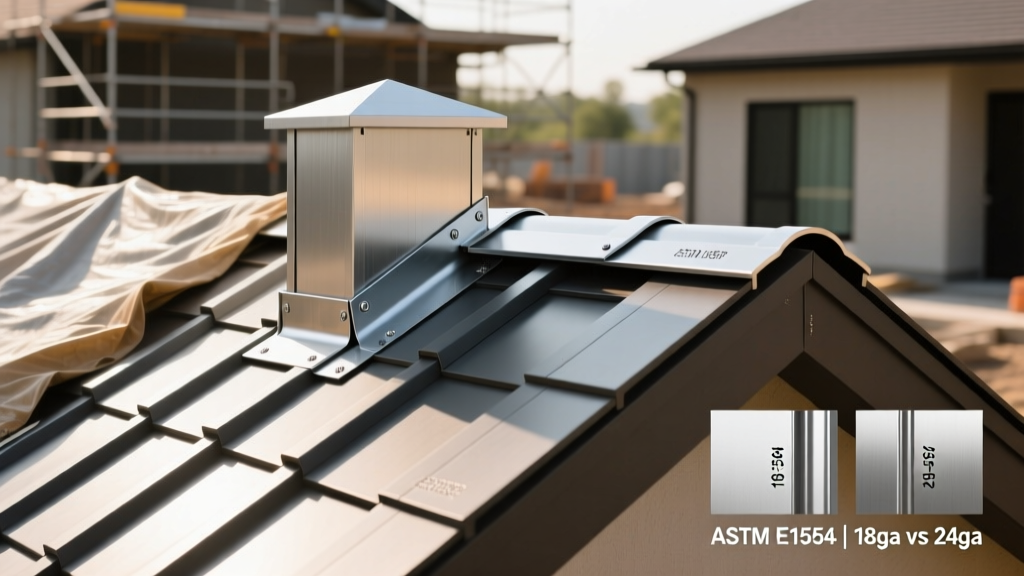
Roof flashing is the primary defense against water intrusion at intersections, penetrations, and transitions. Selecting the wrong gauge, ignoring thermal expansion coefficients, or pairing incompatible metals leads to galvanic corrosion, thermal tearing, and catastrophic leaks. This guide details the exact performance ratings, ASTM specifications, and dimensional requirements for flashing roof components in 2026, moving beyond basic installation steps to focus on the material science and engineering tolerances that dictate long-term system survival.
Governing ASTM and SMACNA Specifications
Every high-performance flashing roof system must adhere to strict manufacturing and material standards. The SMACNA Architectural Sheet Metal Manual provides the baseline for fabrication, while ASTM International governs the metallurgical properties of the base materials. Specifying materials without referencing these codes leaves buildings vulnerable to premature degradation.
| Flashing Material | Governing ASTM Standard | Minimum Roofing Grade / Coating | Primary Application |
|---|---|---|---|
| Cold Rolled Copper | ASTM B370 | H00 (Cold Rolled 1/8 Hard) | Chimney crickets, valleys, parapet coping |
| Galvanized Steel | ASTM A653 | G90 Coating (0.90 oz/sq ft) | Step flashing, drip edge, pipe boots |
| Aluminum | ASTM B209 | 3003-H14 Alloy | Drip edge, gravel stops, fascia |
| Lead-Coated Copper | ASTM B749 | Class 1 (16 oz copper + 1.5 oz lead) | Historic restorations, masonry reglets |
| Stainless Steel | ASTM A240 | Type 304 or 316 | Coastal environments, high-acid runoff |
Minimum Thickness and Gauge Requirements
One of the most common failure modes in residential and commercial roofing is the use of builder-grade, ultra-thin flashing. When evaluating flashing roof materials, thickness must be measured in decimal inches or ounces per square foot (for copper), rather than nominal gauge numbers, which can vary between manufacturers.
Never specify '26 gauge steel' on architectural drawings without defining the decimal equivalent. A manufacturer's tolerance can result in a 10% variance in actual thickness. Always specify the minimum decimal inch thickness (e.g., 0.0179'') to ensure the material possesses the necessary tensile strength to resist wind uplift and mechanical damage from hail or foot traffic.
Dimensional Tolerances by Material
- Copper: 16 oz (0.0216'') is the absolute minimum for flat-lock seams and step flashing. For continuous edge metal, standing seams, or parapet coping, 20 oz (0.027'') or 24 oz (0.0323'') is required to prevent oil-canning and wind flutter.
- Galvanized Steel: 26 gauge (0.0179'') is the minimum for concealed step flashing. 24 gauge (0.0239'') is mandatory for exposed continuous base flashing and edge metal.
- Aluminum: 0.032'' is the minimum thickness for any structural or exposed flashing component. Thinner 0.027'' aluminum is prone to tearing when formed into tight inside/outside corners.
Thermal Expansion Coefficients and Cleat Spacing
Metals expand and contract at vastly different rates as ambient temperatures fluctuate. If a flashing roof component is rigidly fastened without accommodating this movement, the metal will buckle, tear at the fastener holes, or pull away from the substrate. According to the Copper in Architecture Design Handbook, proper slip cleat design is non-negotiable for runs exceeding 10 feet.
| Material | Coefficient of Expansion (in/in/°F) | Movement per 100 ft (100°F temp change) | Maximum Continuous Run (Fixed) |
|---|---|---|---|
| Aluminum | 0.0000129 | 1.55 inches | 35 feet |
| Copper | 0.0000093 | 1.12 inches | 40 feet |
| Galvanized Steel | 0.0000065 | 0.78 inches | 60 feet |
| Stainless Steel | 0.0000056 | 0.67 inches | 70 feet |
Fastening Protocol: For continuous fascia or gravel stop flashing, fasteners must be placed in slotted holes (minimum 1/4'' x 3/4'') spaced no more than 12 inches on center (O.C.). The fastener should be centered in the slot and tightened just enough to hold the metal snugly while allowing lateral movement. Never use neoprene-washer screws in slotted holes; the washer will bind the metal and prevent expansion, leading to catastrophic tearing.
Galvanic Compatibility Matrix
Galvanic corrosion occurs when two dissimilar metals are in electrical contact in the presence of an electrolyte (rainwater, condensation, or salt spray). The less noble metal (anode) will corrode rapidly to protect the more noble metal (cathode). When designing a flashing roof system, dielectric separation is required if incompatible metals must be used.
| Primary Flashing Metal | Safe Contact Metals | Incompatible Metals (Requires Separation) |
|---|---|---|
| Copper | Lead, Stainless Steel (300 series) | Aluminum, Galvanized Steel, Zinc |
| Galvanized Steel | Aluminum, Zinc | Copper, Lead, Stainless Steel |
| Aluminum | Galvanized Steel, Zinc | Copper, Lead, Bare Steel |
| Stainless Steel | Copper, Lead | Galvanized Steel, Aluminum, Zinc |
Even if metals do not physically touch, copper runoff will rapidly destroy aluminum gutters, galvanized steel roofs, and zinc flashings. If a copper parapet coping is installed above an aluminum roof edge, you must install a clear anodized aluminum or TPO catch-tray to divert the copper-laden water away from the lower dissimilar metals.
Single-Ply Membrane Flashing Specs (TPO, PVC, EPDM)
On commercial flat roofs, flashing roof details are often executed using the same membrane as the field of the roof. The NRCA Roofing Manual: Membrane Roof Systems dictates strict thickness and reinforcement requirements for these transition areas, as they endure higher mechanical stress than the field membrane.
Material Specifications for Membrane Flashing
- TPO (ASTM D6878): Flashing membranes must be a minimum of 60 mils thick. For outside corners, pipe boots, and high-tension areas, the TPO must be reinforced with a polyester scrim to prevent splitting under thermal tension. Unreinforced TPO is only acceptable for flat, low-tension wall transitions.
- PVC (ASTM D4434): Minimum 50 mils for flashing. PVC flashing must be heat-welded at a minimum temperature of 950°F to 1,100°F, creating a monolithic seam that is actually stronger than the parent membrane. Solvent welding is strictly prohibited on modern PVC formulations.
- EPDM (ASTM D4637): Minimum 45 mils for uncured flashing (used for complex pipe penetrations and irregular corners) and 60 mils for cured flashing (used for straight wall terminations). Uncured EPDM must be vulcanized using a primer and seam tape, requiring a 24-hour cure time before water exposure.
Termination Bar Requirements
Membrane flashing must be secured at the top edge using a termination bar. The bar must be extruded aluminum (minimum 1/8'' thick, 1'' wide), pre-punched with 1/4'' holes at 8'' O.C. The top edge of the termination bar must be sealed with a continuous 3/8'' bead of polyurethane or TPO-compatible lap sealant. Never use silicone sealant on single-ply roofs; it will not adhere to the membrane and will fail within two years.
Wind Uplift and Edge Metal Performance
Perimeter edge metal, gravel stops, and fascia flashing are the most vulnerable components during high-wind events. The ANSI/SPRI ES-1 standard outlines the testing and performance criteria for edge systems on low-slope roofs. In 2026, building codes in high-velocity hurricane zones (HVHZ) require edge metal to withstand design pressures exceeding 120 PSF.
To achieve these ratings, the flashing roof edge system must utilize a two-piece design: a continuous cleat fastened to the structural deck, and a face piece that snaps into the cleat. The fastener pull-out resistance is the limiting factor in these systems:
- Structural Concrete: Minimum 400 lbs pull-out per fastener (using #14 x 1-3/4'' hex washer head screws).
- Steel Decking (22 ga): Minimum 200 lbs pull-out per fastener (using #12 x 1-1/4'' self-drilling TEK screws).
- Wood Blocking: Minimum 150 lbs pull-out per fastener (using #14 x 2'' wood screws, embedded at least 1'' into the blocking).
Common Installation Failure Modes to Avoid
- Omission of End-Dams: When base flashing terminates at a scupper or roof drain, installers often leave the end open. An end-dam (a soldered or welded fold closing the end of the flashing channel) is mandatory to prevent wind-driven rain from bypassing the membrane and entering the insulation layer.
- Overdriving Fasteners: Using high-torque impact drivers on termination bars often strips the neoprene washers or crushes the metal, destroying the clamping force. Fasteners must be driven with a clutch-adjusted drill to a flush fit, never countersunk.
- Thermal Bowing of Long Fascia: On runs exceeding 40 feet without expansion joints, dark-colored aluminum or steel fascia will absorb solar radiation, reaching temperatures 40°F higher than ambient. Without a slip joint every 20 feet, the metal will bow outward, breaking the sealant joint at the wall interface.
Specifying the correct flashing roof materials requires a rigorous understanding of metallurgy, thermal dynamics, and structural load paths. By adhering strictly to ASTM material grades, enforcing decimal thickness minimums, and respecting galvanic boundaries, roofing professionals can deliver systems that perform flawlessly for decades, regardless of the environmental stresses they face.