Concrete Slab Foundation Specifications and Load Ratings
Review critical concrete slab foundation specifications, including PSI ratings, rebar sizing, vapor barriers, and ASTM standards for structural integrity.
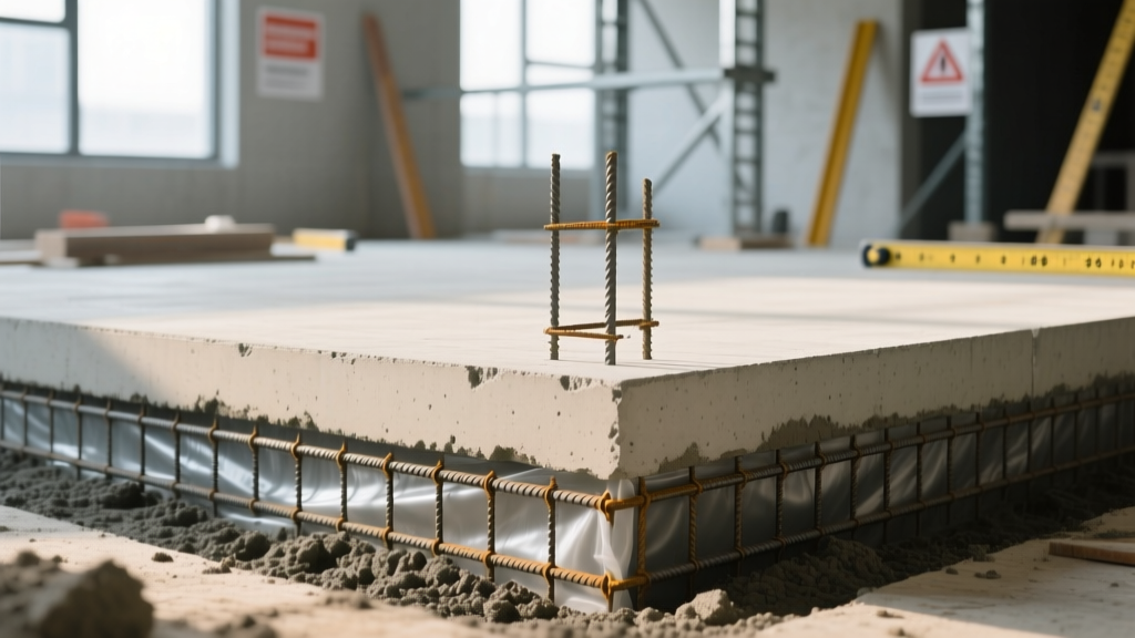
Core Compressive Strength and Mix Design Parameters
Engineering a high-performance concrete slab foundation requires strict adherence to mix design specifications that balance workability with long-term dimensional stability. For standard residential and light-commercial slab-on-grade construction, the baseline compressive strength requirement is 3,000 PSI (21 MPa) at 28 days. However, for post-tensioned slabs, expansive soil conditions, or heavy commercial loads, structural engineers routinely specify 4,000 PSI to 5,000 PSI (28 to 34 MPa) mixes.
The water-cement (w/c) ratio is the single most critical variable governing the slab's permeability and shrinkage potential. Current best practices mandate a maximum w/c ratio of 0.45 for interior slabs and 0.40 for exterior slabs exposed to deicing chemicals. Exceeding these thresholds increases capillary porosity, directly reducing the concrete's resistance to moisture vapor transmission and sulfate attack.
Air Entrainment for Freeze-Thaw Durability
For exterior concrete slab foundations or unconditioned garage slabs in regions subject to freeze-thaw cycles, air entrainment is non-negotiable. Specifications must call for 5% to 7% entrained air content, measured via ASTM C231. The microscopic air voids provide relief chambers for expanding water during freezing, preventing surface scaling and internal micro-fracturing.
Subgrade Preparation and Vapor Barrier Specifications
A concrete slab foundation is only as stable as the soil beneath it. Subgrade preparation must achieve a minimum 95% Standard Proctor density (ASTM D698) or 90% Modified Proctor density (ASTM D1557) for the top 6 inches of native soil. Soft spots or organic topsoil must be excavated and replaced with structural fill.
Over the compacted subgrade, a 4-inch layer of 3/4-inch minus crushed aggregate base course is placed and mechanically compacted. This capillary break prevents groundwater from wicking upward and provides a stable, uniform support plane that minimizes differential settlement.
Vapor Retarder Mandates
Moisture vapor emission through the slab is a primary cause of flooring adhesive failure and indoor air quality degradation. According to the American Concrete Institute (ACI) and current building codes, a Class A vapor retarder is required beneath all interior concrete slabs where moisture-sensitive floor coverings will be installed.
- Material: Cross-laminated polyethylene or polyolefin sheeting.
- Thickness: Minimum 15 mil (0.015 inches) to resist puncture during rebar placement and concrete pouring.
- Standard: Must comply with ASTM E1745, demonstrating a water vapor permeance of less than 0.03 perms after conditioning.
- Seaming: All overlaps must be a minimum of 6 inches, sealed with manufacturer-approved moisture-resistant tape.
As noted by the Portland Cement Association, placing the vapor retarder directly beneath the slab (rather than over a sand blinding layer) is the current industry consensus to eliminate the hidden water reservoir that causes prolonged drying times and excessive curling.
Structural Reinforcement Matrix
Reinforcement strategy dictates the slab's ability to span soft subgrade spots and resist tensile stresses induced by shrinkage and thermal gradients. The choice between Welded Wire Mesh (WWM), conventional rebar, and post-tensioning depends on soil plasticity and structural load requirements.
| Reinforcement Type | Standard Specification | Primary Application | Placement Depth |
|---|---|---|---|
| Welded Wire Mesh (WWM) | 6x6 W1.4xW1.4 (ASTM A1064) | Light residential, stable soils, shrinkage control | Upper third of slab (2 inches down in a 6-inch slab) |
| Conventional Rebar Grid | #4 (1/2') or #5 (5/8') Grade 60 (ASTM A615) | Commercial, heavy point loads, moderate expansive soils | Mid-depth, supported on 2-inch concrete dobies |
| Post-Tensioning (PT) | 270 ksi low-relaxation 1/2' strand (ASTM A416) | Highly expansive clays, large column-free spans | Harped profile (mid-depth at edges, upper third at mid-span) |
Jointing Tolerances and Curling Mechanics
Concrete shrinks as it cures. If this shrinkage is restrained by the subgrade or reinforcement, tensile stresses build until the concrete cracks. A properly engineered concrete slab foundation uses a strategic jointing plan to force cracking to occur in straight, hidden lines.
Contraction (Control) Joints
Contraction joints should be sawcut within 4 to 12 hours of placement, as soon as the concrete is hard enough to resist raveling but before internal tensile stresses exceed the concrete's early tensile strength. According to the National Ready Mixed Concrete Association (NRMCA), joint spacing should not exceed 24 to 30 times the slab thickness. For a standard 4-inch residential slab, maximum joint spacing is 10 to 12 feet. The sawcut depth must be exactly 25% to 33% of the total slab thickness to create a sufficient plane of weakness.
Isolation and Construction Joints
Isolation joints (full-depth, pre-molded filler material) are required wherever the slab abuts vertical structures such as foundation walls, columns, or plumbing penetrations. These joints decouple the slab, allowing independent horizontal movement and preventing stress transfer that leads to corner spalling.
'Curling occurs when the top surface of the slab dries and shrinks faster than the bottom surface, which is restrained by the moist subgrade. To mitigate curling, minimize the water content in the mix, use a high-quality 15-mil vapor barrier directly under the slab, and avoid excessive troweling which traps water and fines at the surface.'
Field Quality Assurance and ASTM Testing Protocols
Specifications are only effective if verified through rigorous field testing. The following ASTM protocols must be executed for every 50 to 100 cubic yards of concrete placed in a slab foundation:
- Slump Test (ASTM C143): Verifies workability and water content. Must be performed before any admixtures or water are added at the site.
- Air Content (ASTM C231): Uses a pressure meter to ensure entrained air falls within the 5% to 7% tolerance for freeze-thaw durability.
- Temperature Measurement (ASTM C1064): Ensures concrete is placed between 50°F and 90°F. Extreme temperatures require specific hot-weather or cold-weather concreting plans per ACI 305 and ACI 306.
- Cylinder Casting (ASTM C31): A minimum of two sets of 4x8 or 6x12 inch cylinders must be cast per 100 cubic yards. One set is cured in a field box (matching slab conditions) for stripping strength, and the other is sent to a lab for standard 28-day moist curing to verify the specified compressive strength (ASTM C39).
By enforcing these precise material specifications, subgrade tolerances, and testing protocols, engineers and contractors can deliver a concrete slab foundation that meets the rigorous load-bearing and moisture-mitigation demands of modern construction.