Concrete Wall Performance Ratings: Fire, Acoustic, and Load Specs
Master concrete wall performance ratings with exact specs for fire resistance, acoustic STC scores, and load-bearing capacities to meet modern building codes.
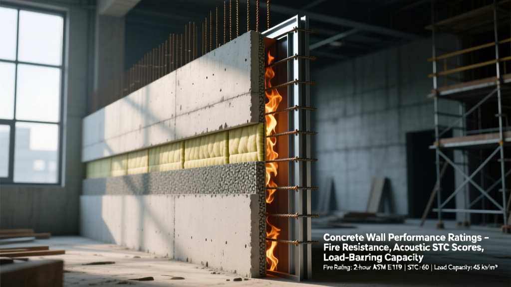
Navigating Concrete Wall Performance Specifications
Specifying a concrete wall requires moving beyond basic compressive strength to evaluate multi-axis performance ratings. Structural engineers and architects must align material properties with International Building Code (IBC) mandates, American Concrete Institute (ACI) standards, and project-specific environmental loads. The performance of a concrete wall is dictated by its thickness, aggregate composition, reinforcement detailing, and finishing assemblies. This guide details the exact technical specifications for fire resistance, acoustic isolation, structural load-bearing, and thermal mass to ensure code compliance and long-term durability.
Fire Resistance Ratings (ASTM E119 / UL 263)
Concrete is inherently non-combustible, but its fire-resistance rating—defined as the duration it can contain a fire and maintain structural integrity—is strictly governed by wall thickness and aggregate type. Under IBC Table 721.1.1.2, the minimum equivalent thickness required to achieve specific hourly ratings varies significantly based on the thermal conductivity of the aggregate used in the mix.
Minimum Equivalent Thickness for Fire Ratings
| Fire Rating | Siliceous Aggregate | Carbonate Aggregate | Lightweight Aggregate |
|---|---|---|---|
| 1-Hour | 3.5 inches | 3.2 inches | 2.7 inches |
| 2-Hour | 5.0 inches | 4.6 inches | 3.6 inches |
| 3-Hour | 6.2 inches | 5.7 inches | 4.4 inches |
| 4-Hour | 7.0 inches | 6.6 inches | 5.1 inches |
For walls requiring a 2-hour rating in a commercial occupancy, specifying a 6-inch lightweight concrete wall provides a built-in safety margin while reducing dead load on the foundation. For detailed mix designs and historical fire testing data, refer to the Portland Cement Association's fire resistance guidelines.
Acoustic Performance: STC and OITC Metrics
Sound isolation in concrete walls is measured using two distinct metrics: Sound Transmission Class (STC) for airborne noise (speech, media) and Outdoor-Indoor Transmission Class (OITC) for low-frequency exterior noise (traffic, aircraft). Because concrete possesses high mass, it naturally blocks airborne sound, but rigid connections and flanking paths can severely degrade field performance.
Bare vs. Finished Assembly Ratings
- 6-inch Bare Cast-in-Place Wall (145 pcf): Yields an STC of 52 and OITC of 48. Sufficient for interior demising walls in multi-family residential, but inadequate for high-privacy zones.
- 8-inch Bare CMU Wall (Grouted, 135 pcf): Yields an STC of 54. The hollow cells, even when grouted, create slight resonance vulnerabilities at specific low frequencies.
- 6-inch Concrete Wall with Decoupled Finish: Adding 1/2-inch gypsum board mounted on resilient channels with 2-inch fiberglass batt insulation in the cavity pushes the assembly STC to 62+ and OITC to 55+. This is the required specification for recording studios, luxury multi-family, and healthcare facilities.
Structural Load-Bearing and Slenderness Limits
Structural concrete walls act as shear walls, bearing walls, or basement retaining walls. The governing standard is ACI 318 (Building Code Requirements for Structural Concrete). The two primary performance constraints are compressive strength ($f'_c$) and the slenderness ratio ($h/t$).
Compressive Strength Specifications ($f'_c$)
Standard residential foundation walls typically specify $f'_c$ of 3,000 to 4,000 psi. However, for mid-rise and high-rise commercial shear walls subjected to severe seismic or wind uplift forces, engineers routinely specify $f'_c$ between 6,000 and 10,000 psi. High-strength mixes require strict water-to-cement ratios (typically below 0.35) and the inclusion of supplementary cementitious materials (SCMs) like silica fume or fly ash to manage the heat of hydration and prevent thermal cracking during the curing process.
Slenderness Ratio ($h/t$) Restrictions
The unsupported height ($h$) to thickness ($t$) ratio dictates the wall's susceptibility to buckling under axial loads. According to ACI 318 empirical design methods:
- Bearing Walls (Solid Rectangular Cross-Section): Maximum $h/t$ ratio of 25. (e.g., A 10-foot unsupported wall requires a minimum thickness of 4.8 inches, practically rounded to 5 or 6 inches).
- Non-Bearing Walls: Maximum $h/t$ ratio of 50, allowing for thinner architectural or veneer-backed concrete panels.
- Basement Retaining Walls: Governed by lateral earth pressure rather than pure axial slenderness. Minimum thickness is generally 8 inches, with 10 to 12 inches required for expansive clay soils or surcharge loads (e.g., driveways adjacent to the foundation).
For comprehensive load tables and reinforcement detailing requirements, consult the American Concrete Institute (ACI) standards library.
Thermal Mass and Energy Code Compliance
Concrete has a notoriously low R-value (approximately R-0.1 per inch for normal-weight concrete). A solid 8-inch concrete wall yields a center-of-cavity R-value of less than 1.0. However, evaluating concrete walls purely on steady-state R-value is a critical error in building science. Concrete's primary thermal benefit is its thermal mass—the ability to absorb, store, and slowly release heat, which flattens peak HVAC loads.
To meet International Energy Conservation Code (IECC) requirements, concrete walls must be insulated. The placement of the insulation drastically alters the wall's hygrothermal performance:
| Insulation Strategy | Thermal Performance | Moisture & Condensation Risk | Best Application |
|---|---|---|---|
| Exterior Only (Rigid Foam) | High. Continuous insulation eliminates thermal bridging. Mass is inside the thermal envelope. | Low. Concrete stays warm, preventing interior condensation. | Heating-dominated climates; commercial exteriors. |
| Interior Only (Batt/Foam) | Moderate. Thermal bridging occurs through concrete studs or furring. | High. Warm interior moisture can condense on the cold concrete surface behind the insulation. | Avoid in cold climates unless a Class I vapor retarder is perfectly detailed. |
| Split Insulation (ICF) | Very High. Typical R-22 to R-26. Concrete mass is sandwiched and highly protected. | Very Low. Foam layers act as inherent vapor and air barriers. | Residential basements; high-performance net-zero envelopes. |
For deep-dive hygrothermal modeling of concrete wall assemblies, the Building Science Corporation's guide on concrete walls provides essential detailing for moisture management and insulation placement.
System Selection Matrix: Cast-in-Place vs. Precast vs. ICF
Choosing the right concrete wall system requires balancing performance specs with site logistics and schedule constraints.
- Cast-in-Place (CIP): Offers the highest structural continuity and shear capacity. Ideal for complex geometries, seismic zones, and deep basements. Requires extensive formwork and curing time (typically 7 to 28 days to reach design strength). Tolerances are highly dependent on carpentry formwork skills.
- Precast Tilt-Up / Panels: Factory-controlled curing ensures exact $f'_c$ and superior surface finishes. Erection is rapid, but panel joints require meticulous fire-stopping and acoustic sealing to maintain the performance ratings of the monolithic sections. Best for large commercial footprints and warehouses.
- Insulating Concrete Forms (ICF): Integrates structure, insulation, and air/water barriers in a single step. Yields consistent 6-inch structural cores with R-22+ continuous insulation. Limitations include lower shear capacity compared to thick CIP walls, requiring heavier reinforcement grids in high-wind zones.
Final Specification Checklist
Before finalizing construction documents, verify the following parameters against your local jurisdiction's amendments to the IBC and IECC:
- Confirm aggregate type aligns with the required fire-resistance thickness.
- Validate that the specified $f'_c$ and $h/t$ ratio satisfy both gravity and lateral load combinations.
- Ensure acoustic detailing addresses flanking paths at floor-to-wall and ceiling-to-wall intersections.
- Specify insulation placement based on the project's specific climate zone dew point calculations.