Wire Mesh vs Rebar in Concrete: Installation & Load Guide
Master the wire mesh vs rebar in concrete debate. This installation guide covers load matrices, lap splices, chair heights, and 2026 material costs.
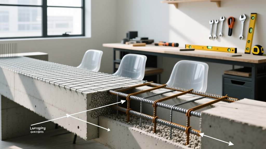
The Structural Divide: Tensile Strength vs. Crack Control
Concrete possesses immense compressive strength but is inherently weak in tension. When a slab bends under load or shrinks during the curing process, tensile stresses cause cracking. The debate over wire mesh vs rebar in concrete is not about which material is universally superior; it is about matching the reinforcement to the specific mechanical demand of the slab. Steel rebar (ASTM A615) is designed to absorb structural loads and resist bending moments, while welded wire mesh (WWM, ASTM A1064) is engineered to hold shrinkage and temperature cracks tightly together.
According to the Portland Cement Association, improper reinforcement selection or installation is the leading cause of premature slab failure. Installing the wrong material—or installing the correct material at the wrong depth—renders the steel useless.
Decision Matrix: When to Deploy Mesh, Rebar, or Both
Use the following framework to determine the correct reinforcement strategy based on slab thickness, subgrade conditions, and anticipated loads.
| Application | Slab Thickness | Primary Reinforcement | Secondary / Supplemental |
|---|---|---|---|
| Residential Patios & Walkways | 4 inches | 6x6 W1.4xW1.4 Wire Mesh | Fiber mesh (optional) |
| Standard Driveways (Passenger Vehicles) | 4 to 5 inches | 6x6 W2.0xW2.0 Wire Mesh | #3 Rebar at edges / joints |
| Heavy Driveways (RVs / Dump Trucks) | 5 to 6 inches | #4 Rebar Grid (18" OC) | 6x6 W1.4xW1.4 Wire Mesh |
| Garage Floors & Shop Slabs | 4 to 6 inches | #4 Rebar Grid (16" to 24" OC) | Saw-cut control joints |
| Structural Foundations / Pile Caps | 8+ inches | #5 or #6 Rebar (Engineered) | Dowel bars for vertical ties |
Installation Protocol: Welded Wire Mesh (WWM)
Welded wire mesh is sold in flat sheets (typically 5x150 feet or 5x50 feet) or rolls. The most common residential specification is 6x6 W1.4xW1.4 (10-gauge wire with 6-inch grid spacing). For driveways, upgrade to W2.0xW2.0 (9-gauge).
Step-by-Step Mesh Installation
- Subgrade Preparation: Ensure the compacted subgrade is level and covered with a 10-mil or 15-mil polyethylene vapor barrier. Punctures in the vapor barrier from sharp aggregate will compromise moisture control.
- Layout and Overlap: Lay the mesh sheets flat. Where sheets meet, you must overlap them by at least one full grid square (typically 6 inches). According to the Wire Reinforcement Institute, failing to lap the mesh creates a continuous hinge point where cracks will inevitably form.
- Elevation (The Critical Step): Mesh must sit in the upper third of the slab to control surface cracking. For a 4-inch slab, the mesh should be elevated 2 inches off the subgrade. Use high-density polyethylene (HDPE) concrete chairs or continuous rebar bolsters spaced every 4 feet. Never rely on pulling the mesh up during the pour—this results in inconsistent placement.
- Edge Clearances: Keep the mesh 1 to 2 inches away from the forms. Exposed mesh at the edges will rust and cause the concrete perimeter to spall.
The most common installation error with wire mesh occurs during the concrete pour. As workers walk on the mesh to screed the surface, the chairs collapse, pushing the steel to the very bottom of the slab. Mesh at the bottom of a slab provides zero tensile crack control for the surface. Always use heavy-duty bolsters and pour from the edge inward, stepping only on the freshly placed concrete.

Installation Protocol: Steel Rebar (#3 and #4)
Rebar provides the structural backbone for slabs subjected to heavy point loads or poor subgrade conditions. #3 rebar (3/8-inch diameter) is suitable for light structural edges, while #4 rebar (1/2-inch diameter) is the standard for garage floors and heavy driveways.
Step-by-Step Rebar Installation
- Grid Spacing: Lay out the rebar in a grid pattern. Standard spacing is 16 inches or 24 inches on center (OC), depending on the engineer's specifications or local building codes.
- Tying the Intersections: Use 16-gauge annealed tie wire to secure the intersections. You do not need to tie every single intersection; tying every other intersection (skip-tying) is sufficient to hold the grid together during the pour. Use a rebar twister tool to pull the wire tight and snap the tail inward so it doesn't protrude to the surface.
- Lap Splices: When rebar runs must be continued, they must overlap. The standard rule of thumb is 35 to 40 bar diameters. For #4 rebar (0.5-inch diameter), a 40-diameter lap splice equals exactly 20 inches of overlap. Secure the lap with at least three ties.
- Setting the Cover: Rebar requires a minimum of 1.5 to 2 inches of concrete cover on the bottom and sides to prevent moisture intrusion and subsequent rust-jacking. Use 2-inch heavy-duty bar chairs (point chairs for single bars, line chairs/bolsters for continuous runs).
"Proper concrete cover is non-negotiable. For every millimeter of cover lost to poor placement, the time to corrosion initiation of the embedded steel is reduced exponentially." — American Concrete Institute (ACI) Durability Guidelines
Critical Installation Failures and Mitigation
Even with the correct material selected, poor execution leads to catastrophic slab failure. Monitor your crew for these specific edge cases:
- Rebar Spalling (Rust-Jacking): If rebar is placed too close to the surface (less than 1.5 inches of cover), water penetrates the concrete matrix. When steel rusts, it expands up to 7 times its original volume, causing the concrete above it to crack and pop off in large chunks. Fix: Inspect chair heights before the truck arrives. Kick or replace any crushed chairs.
- Cold Joint Weaknesses: If a concrete truck is delayed and the first half of the slab begins to set before the second half is poured, a cold joint forms. Standard mesh will not bridge this gap effectively. Fix: Drive #4 rebar dowels horizontally into the fresh edge every 18 inches to mechanically lock the two pours together.
- Saw-Cut Timing: Reinforcement controls the width of the crack, but it does not dictate where the crack occurs. You must still saw-cut control joints at a depth of 25% of the slab thickness (1 inch for a 4-inch slab) within 4 to 12 hours of the finish. If you wait 24 hours, the slab will have already experienced uncontrolled random cracking, rendering your steel installation moot.
2026 Material and Labor Cost Breakdown
Budgeting for reinforcement requires looking beyond the raw material cost. Labor and accessory costs (chairs, tie wire) significantly impact the final price per square foot. Below are average national estimates for 2026.
| Material Type | Raw Material Cost (per sq. ft.) | Accessories & Labor Adder | Total Installed Cost (per sq. ft.) |
|---|---|---|---|
| 6x6 W1.4xW1.4 Mesh (10ga) | $0.18 - $0.24 | $0.08 (chairs/labor) | $0.26 - $0.32 |
| 6x6 W2.0xW2.0 Mesh (9ga) | $0.28 - $0.35 | $0.10 (chairs/labor) | $0.38 - $0.45 |
| #3 Rebar Grid (24" OC) | $0.35 - $0.45 | $0.25 (chairs/tying) | $0.60 - $0.70 |
| #4 Rebar Grid (16" OC) | $0.65 - $0.85 | $0.35 (chairs/tying) | $1.00 - $1.20 |
Note: Prices fluctuate based on regional steel tariffs and local labor rates. Always secure quotes from local suppliers within 30 days of your pour date.
Hybrid Reinforcement: The Heavy-Duty Solution
For commercial shop floors, RV pads, or slabs built over expansive clay soils, relying on a single reinforcement type is often insufficient. Hybrid reinforcement combines the structural bending resistance of a #4 rebar grid (spaced at 24 inches OC) with a top layer of 6x6 W1.4xW1.4 wire mesh.
In this configuration, the rebar is elevated on 3-inch chairs to sit in the lower third of a 6-inch slab, handling heavy point loads from vehicle lifts or machinery. The wire mesh is elevated on 1.5-inch chairs to sit in the upper third, tightly controlling surface shrinkage cracks. This dual-layer approach increases material and labor costs by approximately 40%, but it is the industry standard for high-stress environments where joint spalling and structural deflection cannot be tolerated.
Written by
Priya KapoorPriya Kapoor is a real estate market analyst and construction economics researcher with expertise in housing affordability, development feasibility, and infrastructure investment. She holds a Master of Regional Planning from Cornell University and previously worked as a senior analyst at CBRE's Investment Properties group, where she modeled returns for $4B in mixed-use development pipelines. Priya now runs an independent research practice advising developers, municipalities, and REITs on construction cost forecasting and market timing. She publishes the quarterly "BuildMat Market Pulse" report tracking material price indices across 12 commodity categories. Based in Austin, TX, Priya serves on the board of Habitat for Humanity Austin and is a marathon runner.
More from Priya Kapoor
View all
Construction Cost
Cost to Build a 1600 Sq Ft Home in 2026: Full Breakdown
Accurate 2026 cost to build a 1600 sq ft home—material, labor, and regional pricing breakdowns included. Plan your budget with real-time estimates.
Aug 11, 2026
Wood & Lumber
Name the Types of Wood for Pressure Treatment and Preservation
Learn how to name the types of wood best suited for pressure treatment. Compare species treatability, chemical retention levels, and 2026 preservation costs.
Aug 4, 2026

Stone & Masonry
Stone Veneer Suppliers Lindenhurst: 2026 Cost Analysis
Analyze 2026 stone veneer costs in Lindenhurst, NY. Compare local supplier pricing, delivery fees, and Suffolk County installation labor rates.
Aug 4, 2026