Cable Deck Railing Installation: Step-by-Step Pro Guide
Master cable deck railing installation with our pro guide. Learn post spacing, tensioning specs, and code compliance for a flawless outdoor view.
Pre-Installation: Code Compliance and Material Selection
Installing a cable deck railing system requires strict adherence to structural tolerances and building codes. Unlike traditional wood balusters, cable systems rely on continuous tension to meet safety standards. Before cutting any materials, verify your local adoption of the International Residential Code (IRC). Under IRC Section R312.1, deck guards must be a minimum of 36 inches high for residential applications and 42 inches for commercial. More critically, the system must pass the 4-inch sphere rule: a 4-inch sphere cannot pass through any opening in the guard. Because cables are flexible, this rule is evaluated after the cables are fully tensioned.
For materials, specify 1/8-inch diameter, 1x19 strand, Type 316 marine-grade stainless steel cable. Type 304 stainless steel is prone to pitting and crevice corrosion in coastal or high-humidity environments. The 1x19 strand configuration provides the necessary rigidity and smooth exterior finish, whereas 7x7 or 7x19 strands are too flexible and rough for architectural railing applications.
Step 1: Post Installation and Structural Reinforcement
The most common point of failure in cable railing is post deflection. When you tension a run of ten cables to 200 lbs each, you exert 2,000 lbs of inward lateral pull on the end posts. Standard 4x4 wood posts anchored only to the deck rim joist will bow inward, ruining the tension and violating the 4-inch sphere code.
Spacing and Anchoring Specs
- Maximum Post Spacing: 8 feet on center. While some manufacturers claim 10 feet is acceptable, 8 feet minimizes cable sag and reduces the required tensioning force.
- End Post Sizing: Use a minimum 6x6 wood post or a 2.5-inch square structural aluminum post for terminal (end) and corner posts to resist the cumulative tension load.
- Anchoring: Through-bolt intermediate posts with 1/2-inch hot-dipped galvanized carriage bolts. For end posts, use structural steel post bases (like the Simpson Strong-Tie ZPOST or equivalent) bolted directly to the deck framing with 1/2-inch structural lag screws, supplemented by internal blocking.
To counteract the inward pull on end posts, install a rigid structural top rail (such as a 2x6 wood cap or a 2-inch aluminum square tube). This top rail acts as a compression strut, transferring the inward load back into the intermediate posts and keeping the end post plumb. Consult the American Wood Council design guides for specific lateral load transfer calculations on wood framing.
Step 2: Drilling the Tensioning Holes
Precision drilling is non-negotiable. A 1/16-inch misalignment between posts will cause the cable to bind, creating friction that prevents proper tensioning and prematurely wears the stainless steel.
- Use a Drill Jig: Clamp a commercial cable railing drill jig to each post. This ensures hole heights are identical across the entire run.
- Bit Selection: Use a 1/4-inch brad-point or ship auger bit for 1/8-inch cable. The 1/8-inch clearance is required so the swage fittings (which are typically 3/16-inch or 1/4-inch in diameter) can pass through the intermediate posts during threading.
- Prevent Tear-Out: Drill halfway through the post from one side, then meet the hole from the opposite side to prevent wood splintering on the exit point.
Step 3: Threading and Securing the Cables
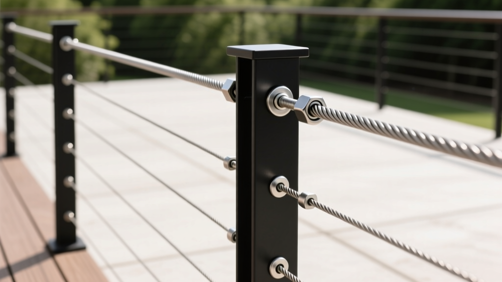
There are two primary termination methods: swage fittings and screw terminals. For a clean, professional finish, hydraulic swage fittings are the industry standard. Screw terminals are bulkier and require more maintenance, as the threads can seize over time in outdoor environments.
| Parameter | Specification | Rationale |
|---|---|---|
| Vertical Spacing | 3.0 inches to 3.25 inches | Ensures 4-inch sphere rule compliance under load. |
| Bottom Cable Clearance | 2.0 inches from deck surface | Prevents debris accumulation and moisture wicking. |
| Target Tension | 150 lbs - 200 lbs per cable | Eliminates sag without over-stressing wood posts. |
| Top Rail Clearance | 3.0 inches below top rail | Maintains uniform visual spacing and code compliance. |
Thread the cable through the intermediate posts. At the tensioning end (usually the end post), attach a stainless steel tensioning turnbuckle or a lag-screw terminal. Leave the turnbuckle fully extended (unscrewed) to allow for maximum take-up during the tensioning phase.
Step 4: Tensioning the Deck Railing Cables
Proper tensioning dictates the longevity and safety of the installation. Do not rely on the 'ping' test (plucking the cable to hear a musical note), as acoustic pitch is highly subjective and varies with cable length.
Pro Technique: Use a digital cable tension gauge (such as the Loos & Co. PT1 or equivalent). Tension the cables in a specific sequence: start with the top and bottom cables to establish the boundary, then work inward toward the center. This distributes the load evenly across the post and prevents the post from twisting.
Tighten the turnbuckles using a wrench until the gauge reads 150 to 200 lbs. Once all cables reach the target tension, lock the turnbuckle nuts in place using a drop of medium-strength threadlocker (like Loctite 243) to prevent vibration from loosening the hardware over time.
Step 5: Crimping and Final Trimming
If using swage fittings, you must compress the metal sleeve onto the cable. Never use manual hand crimpers for 1/8-inch architectural cable. Hand crimpers apply uneven pressure, creating flat spots that reduce the cable's breaking strength by up to 40%.
Use a hydraulic crimper with the exact 1/8-inch die size. Apply pressure until the die fully closes, ensuring a uniform 360-degree compression. After crimping, use a specialized stainless steel cable cutter to trim the excess tail. Do not use standard diagonal cutters or angle grinders, as these will fray the 1x19 strands and leave sharp, dangerous burrs. Cut the cable flush with the end of the swage fitting.
Common Failure Modes to Avoid
- Galvanic Corrosion: If using aluminum posts, you must use nylon or Delrin isolator grommets in the drill holes. Direct contact between 316 stainless steel and aluminum in the presence of rainwater creates a galvanic cell, rapidly corroding the aluminum post.
- Over-Tensioning: Pulling cables past 250 lbs will cause wood posts to bow inward and can strip the threads on stainless steel turnbuckles.
- Crevice Corrosion: In coastal zones, salt accumulates in the microscopic gaps of un-swaged screw terminals. Always specify hydraulic swage fittings for projects within 5 miles of a saltwater coast.
Tool Checklist and 2026 Cost Breakdown
Executing this installation requires specialized tools. Budget for the following equipment and materials based on current 2026 market pricing.
Required Tooling
- Hydraulic swaging tool with 1/8-inch die (Rental: ~$75/day)
- Digital cable tension gauge ($80 - $120)
- Cable railing drill jig ($40 - $90)
- 1/4-inch brad-point drill bit and heavy-duty drill
- Stainless steel wire rope cutters ($35)
Material Cost Estimates (Per 20 Linear Feet of Railing)
| Component | Quantity | Unit Cost (2026) | Total Cost |
|---|---|---|---|
| 316 SS 1/8" Cable (200 ft total) | $0.85 / ft | $170.00 | |
| Hydraulic Swage Fittings | 20 pcs | $4.50 / ea | $90.00 |
| Tensioning Turnbuckles | 10 pcs | $14.00 / ea | $140.00 |
| Intermediate Post Protectors | 20 pcs | $2.00 / ea | $40.00 |
| Estimated Hardware Total (Excluding Posts & Top Rail) | $440.00 | ||
For comprehensive manufacturer specifications and warranty requirements regarding specific swage sleeve dimensions, always refer to the official installation guidelines from major cable railing manufacturers before finalizing your material order. Proper execution of these steps ensures a rigid, code-compliant barrier that preserves your outdoor sightlines for decades.