Building a T Post Fence: Step-by-Step Installation Guide
Learn how to install a T post fence with our step-by-step guide. Covers post spacing, driving techniques, wire tensioning, and bracing for durability.
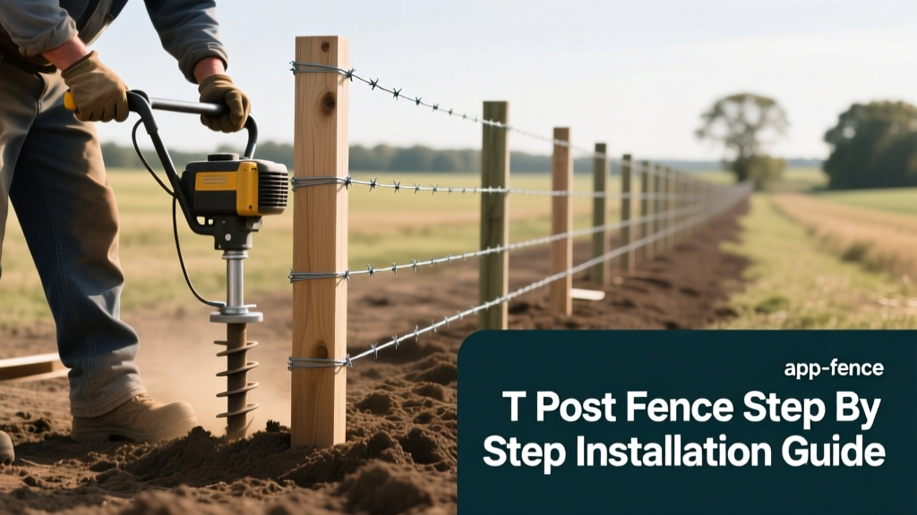
T-post fences remain the most efficient and cost-effective solution for agricultural boundaries, livestock containment, and rural property demarcation. Unlike traditional wood or pipe fencing, steel T-posts offer rapid deployment and high tensile strength, provided they are installed with precise attention to depth, bracing, and wire tensioning. A poorly installed T-post fence will lean, heave, and fail under animal pressure within a single season. This guide details the exact installation procedures, material specifications, and structural frameworks required to build a permanent T-post fence.
Material Specifications and Load Requirements
Selecting the correct T-post weight and height is the first critical decision. T-posts are categorized by their weight per linear foot, which directly correlates to the steel thickness and the size of the anchor plate (spade) at the base. Using undersized posts for high-tension wire or large livestock is the primary cause of fence failure.
| Post Weight (lb/ft) | Standard Heights | Anchor Plate Size | Recommended Wire Count | Best Application |
|---|---|---|---|---|
| 1.01 lb/ft (Light) | 4 ft - 5 ft | 4 x 4 inches | 3 to 4 strands | Garden fencing, temporary poultry, light deer exclusion |
| 1.25 lb/ft (Standard) | 5 ft - 6.5 ft | 6 x 6 inches | 5 to 6 strands | Standard cattle, sheep, woven wire field fences |
| 1.33 lb/ft (Heavy) | 6 ft - 8 ft | 7 x 7 inches | 6 to 8 high-tensile | Heavy cattle, horse corrals, high-tension perimeter fencing |
2026 Pricing Context: Expect to pay between $6.50 and $7.50 for 1.01 lb/ft posts, $8.50 to $9.50 for 1.25 lb/ft posts, and $11.00 to $13.00 for 1.33 lb/ft posts, depending on regional steel tariffs and bulk purchasing volume. Always purchase posts coated in a rust-inhibitive enamel or hot-dipped galvanized finish for permanent installations.
Corner and Gate Bracing Systems (The Failure Point)
T-posts cannot withstand the lateral pull of tensioned wire at corners or gate ends. Relying on T-posts alone for corners will result in the posts leaning inward and the wire sagging within weeks. You must construct a dedicated wooden H-brace or diagonal brace assembly at every corner, gate, and any point where the fence line changes direction by more than 15 degrees.
Building a Standard H-Brace Assembly
- Set the Corner Post: Use a 4-inch to 6-inch diameter pressure-treated wood post (minimum 8 feet long). Set it 3.5 to 4 feet deep in concrete or tamped gravel. The corner post bears 100% of the horizontal wire tension.
- Set the Brace Post: Place a second 4-inch treated wood post exactly 8 feet away from the corner post along the fence line. Set this post 2.5 to 3 feet deep.
- Install the Horizontal Brace: Notch both posts and secure a 4-inch diameter horizontal wood brace between them at a height of roughly 40 inches from the ground. Use 6-inch galvanized lag screws or through-bolts.
- Apply the Diagonal Brace Wire: Wrap 9-gauge high-tensile brace wire around the base of the corner post and the top of the brace post. Pull it tight and secure it using a Gripple tensioner or a hand-crimped wire tightener. This wire transfers the pulling force of the fence wire down into the ground via the corner post.
Site Preparation and Layout Strategy
Before driving a single post, clear the fence line of large rocks, stumps, and heavy brush. Run a mason's string line tightly between your established corner H-braces. This string serves as your absolute guide for alignment.
Spacing Metrics: For standard woven wire or 5-to-6 strand barbed wire, space T-posts 10 to 12 feet apart. For high-tensile smooth wire (which exerts less lateral sag), you can space main T-posts 16 to 20 feet apart. However, when spacing posts wider than 12 feet, install lightweight fiberglass stay posts or 1.01 lb/ft T-posts every 50 feet to prevent the wire from drooping between the main steel posts.
Driving the T-Posts: Techniques and Tool Selection
The structural integrity of a T-post relies entirely on its embedment depth and the engagement of the anchor plate with undisturbed soil.
Depth and Orientation Rules
- Minimum Depth: Drive posts a minimum of 18 inches into the ground. For 6-strand high-tensile fences or regions with heavy clay soils, increase depth to 24 inches.
- Anchor Plate Engagement: The anchor plate (spade) at the bottom of the post must be driven completely below the soil surface. If the plate is left exposed or partially buried, the post will lack lateral stability and will pivot when an animal leans on the wire.
- Stud Orientation: The metal studs (nubs) used to hold the wire clips must always face inward, toward the side where the animal pressure will be applied. This forces the animal to push against the solid steel spine of the post, rather than pushing the wire and clips off the studs.
Wire Attachment and Tensioning Procedures
Attaching wire to a T-post requires specific hardware to prevent galvanic corrosion and wire slippage. Never wrap high-tensile wire directly around the bare steel post; the friction will eventually cut through the wire's galvanized coating, leading to rust and snapping.
Using T-Post Clips
Use 14.5-gauge galvanized T-post clips. Hook the clip over the stud, wrap the ends around the wire, and twist the ends together tightly using fencing pliers. For high-tensile wire, leave a slight gap (about 1/4 inch) between the clip and the wire. This allows the wire to slide slightly during thermal expansion and contraction without snapping the clip.
Tensioning Metrics
Proper tension is non-negotiable for fence longevity. According to Penn State Extension guidelines, under-tensioned wire will sag and tangle, while over-tensioned wire will snap during winter temperature drops.
- 12.5-Gauge High-Tensile Wire: Tension to 150–200 lbs per strand. Use an inline ratchet strainer or a come-along winch at the brace end, and verify the tension with a calibrated fence tension gauge.
- Woven Wire (Field Fence): Tension only until the vertical stay wires are perfectly plumb and the horizontal line wires are straight. Over-tensioning woven wire will distort the knots and permanently weaken the mesh.
Common Installation Failures and Edge Cases
Even with correct materials, environmental factors can compromise a T-post fence. The USDA NRCS Conservation Practice Standards highlight several environmental failure modes that installers must mitigate during construction.
Frost Heave in Expansive Soils
In northern climates with deep frost lines, freezing soil moisture grips the anchor plate and pushes the post upward (frost heave). If your local frost line is 36 inches, but you only drive the post 18 inches deep, the post will rise every winter. Solution: In high-heave zones, drive posts deeper, or use a post-puller in early spring to re-seat heaved posts before the wire is fully tensioned.
Lightning Strikes on High-Tensile Fences
Miles of continuous high-tensile wire act as a massive antenna. A direct or nearby lightning strike can melt the wire at the T-post clips and destroy inline insulators. Solution: Install lightning arrestors (grounding tubes driven 6 feet into the earth) every 1,000 feet along the fence line, and use insulated T-post clips at 500-foot intervals to break the continuous electrical path.
Rocky or Shallow Bedrock Terrain
When the anchor plate hits bedrock at 10 inches, the post cannot be driven deeper, resulting in a weak foundation. Solution: Do not attempt to bend the post or cut the anchor plate off. Instead, drill a 2-inch hole into the bedrock using a rotary hammer, insert a steel rebar pin, and wire the T-post base securely to the pin, backfilling the hole with hydraulic cement.