Step-by-Step Installation Guide for Electric Heated Floor Systems
Master the installation of electric heated floor systems under tile. Learn subfloor prep, mat layout, thinset embedding, and thermostat wiring.
System Selection & Subfloor Prerequisites
Electric heated floor systems transform cold tile, stone, and engineered wood surfaces into radiant comfort zones. Unlike hydronic setups requiring boilers, pumps, and complex manifolds, electric radiant mats operate on standard 120V or 240V circuits. This makes them the definitive choice for bathroom, kitchen, and entryway retrofits where floor height buildup must be minimized. According to the U.S. Department of Energy, electric radiant systems are highly efficient for zone-heating specific rooms, allowing homeowners to lower overall HVAC thermostat settings while maintaining localized comfort.
Before unrolling any heating elements, the structural integrity of the subfloor must be verified. For tile and stone installations, the subfloor deflection limit must strictly meet L/360 standards. If installing over wooden joists, ensure the subfloor consists of minimum 1-1/8-inch tongue-and-groove plywood or OSB. Cement backer board (e.g., HardieBacker or Durock) should be screwed and thinset-bedded over the wood subfloor to decouple the tile assembly from structural movement.
Thermal Break Requirement
Uninsulated subfloors can lose up to 30% of radiant heat downward into the joist cavities. To force heat upward into the flooring, install a thermal break layer. Use 1/4-inch cork underlayment (such as CeraZorb) or extruded polystyrene (XPS) foam boards adhered directly to the subfloor before installing your cement backer board or uncoupling membrane.
Electrical Prerequisites & Load Calculation
Electric heated floor systems draw significant continuous power and require a dedicated circuit. Sharing a circuit with high-draw appliances (like hair dryers or microwaves) will result in nuisance tripping.
- 120V Systems: Ideal for areas under 120 square feet. Draws approximately 1 amp per 10 square feet of heated space.
- 240V Systems: Required for areas exceeding 120 square feet. Halves the amperage draw, allowing a single 20-amp double-pole breaker to handle up to 300 square feet of heating mats.
Per NFPA 70 (National Electrical Code) Article 424, all electric floor heating installations in wet areas (bathrooms, kitchens) must be protected by a Class A Ground Fault Circuit Interrupter (GFCI). Most modern line-voltage radiant thermostats have this GFCI protection built directly into the unit, eliminating the need for a specialized GFCI breaker at the main panel.
Step-by-Step Mat Layout & Routing
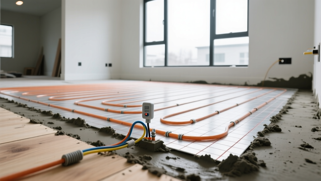
Proper layout prevents cold spots and protects the integrity of the heating wires. Follow this sequence for mapping and securing the mats:
- Map the Exclusion Zones: Maintain a strict 6-inch clearance from walls, vanities, and cabinets. Crucially, maintain an 8-inch clearance from toilet flanges; excessive heat can melt the wax ring, causing sewer gas leaks and water damage.
- Cutting the Mesh: You can freely cut the fiberglass mesh backing to navigate corners, toilets, and odd angles. Never cut, nick, or crimp the actual heating wire. A single nick will create a high-resistance hot spot that will eventually burn out the entire system.
- Wire Spacing: If using loose cable systems (like SunTouch WarmWire) instead of pre-spaced mats, use the manufacturer's spacing strips to maintain exactly 3-inch or 4-inch spacing between wire runs. Inconsistent spacing results in visible thermal striping on the tile surface.
- Secure the Mats: Apply a skim coat of thinset or use double-sided fiberglass installation tape every 12 inches to lock the mats to the subfloor, preventing them from floating when the embedding mortar is applied.
The "cold lead" is the unheated, shielded wire connecting the mat to the thermostat. It must be routed through a 1/2-inch flexible conduit or embedded directly in the thinset. Never overlap the cold lead with the heating wires, and never route it through a wall cavity where it could be pierced by drywall screws or trim nails.
Embedding Techniques: Thinset vs. Self-Leveling Compound
The material used to encapsulate the heating system dictates the longevity of the floor and the compatibility with your chosen finish material.
| Embedding Material | Best For | Application Technique | Key Considerations |
|---|---|---|---|
| Modified Thinset Mortar | Ceramic, Porcelain, Natural Stone Tile | Use a 1/4" x 1/4" square-notched trowel. Press mortar through the mesh to fully encapsulate wires, eliminating air pockets. | Air pockets act as thermal insulators, causing the wire to overheat and fail prematurely. Back-butter large format tiles to ensure 95% mortar coverage. |
| Self-Leveling Compound (SLC) | Luxury Vinyl Plank (LVP), Engineered Wood, Laminate | Prime subfloor first. Pour SLC to a minimum depth of 1/4" over the highest wire point. Use a gauge rake and spike shoes to spread. | SLC provides a perfectly flat surface required for floating floors and LVP. Do not use SLC thinner than manufacturer specs, or it will crack over the wires. |
| Uncoupling Membrane | Tile over questionable subfloors (e.g., Schluter-DITRA-HEAT) | Cables are pressed directly into the fleece-backed membrane studs. Unmodified thinset is used to bond membrane to wood subfloor. | Reduces overall floor height buildup to roughly 1/4". Provides superior crack isolation for natural stone. |
Floor Sensor Placement & Thermostat Wiring
The floor temperature sensor is the brain of the operation. Improper placement is the number one cause of "short cycling" (where the system turns off before the room is actually warm) or complete system failure.
Sensor Routing Rules
- Conduit Protection: Always run the sensor wire through a 3/4-inch flexible PVC or ENT (smurf tube) conduit from the thermostat box down into the floor. If the sensor fails in five years, you can pull it out and push a new one in without ripping up the tile.
- Equidistant Placement: The sensor tip must be placed exactly equidistant between two heating wire runs (typically 1.5 inches from each wire if using 3-inch spacing).
- Never Cross Wires: The sensor wire must never cross over or touch the heating wire. Maintain at least a 1-inch vertical or horizontal separation to prevent electromagnetic interference and false temperature readings.
- Avoid Solar Interference: Do not place the sensor in an area that receives direct, intense sunlight through a window, as this will trick the thermostat into shutting off the system prematurely.
The 3-Stage Ohm Testing Protocol
Do not wait until the tile is laid to discover a broken wire. You must test the system's electrical resistance (measured in Ohms) using a digital multimeter at three distinct phases. Calculate your expected resistance using the formula: Expected Ohms = (Voltage²) / Wattage.
- Test 1 (Out of the Box): Test the resistance between the two power leads, and test continuity between the ground braid and each power lead (should read infinite/OL). Record these exact numbers on the thermostat warranty card.
- Test 2 (Post-Embedding): Immediately after troweling the thinset or pouring the SLC, test again. If a sharp trowel edge nicked a wire during embedding, the resistance will drop to zero (short circuit) or spike to infinite (open circuit). Catching this now allows you to dig out the mortar and repair the wire with a manufacturer-approved heat-shrink splice kit.
- Test 3 (Post-Flooring): Test one final time after the tile is set and grouted, right before connecting the wires to the line-voltage thermostat.
Troubleshooting Common Installation Failures
| Symptom | Probable Cause | Corrective Action |
|---|---|---|
| Thermostat clicks on and off every 2 minutes (Short Cycling) | Floor sensor is placed too close to the heating wire, or sensor is touching the wire. | Disconnect thermostat. Pull sensor wire back 2 inches if in conduit, or re-route via a secondary conduit. Ensure sensor is centered between wire runs. |
| GFCI trips immediately upon powering the system | Heating wire was nicked during thinset application, exposing the inner conductor to the alkaline mortar, causing a ground fault. | Locate the nick using a thermal camera or megohmmeter. Cut out the damaged section and install a waterproof, adhesive-lined heat-shrink splice kit. (Note: This voids some warranties; replacement is preferred if caught before tiling). |
| Floor takes 4+ hours to reach target temperature | Missing thermal break under the heating elements; heat is sinking into the joist cavity. Or, unmodified thinset was used over an uncoupling membrane without proper curing time. | Ensure a cork or XPS thermal break was installed. For future installations, always use a digital thermostat with a "floor limit" setting and an ambient air sensor to maintain baseline heat. |
Installing electric heated floor systems requires meticulous attention to electrical safety, mortar chemistry, and spatial geometry. By adhering to strict wire spacing, utilizing thermal breaks, and executing the 3-stage Ohm testing protocol, you ensure a radiant floor assembly that will operate efficiently and safely for the lifespan of the flooring itself.