Step Flashing Roof Specs: Material Ratings & Performance Data
Analyze step flashing roof specifications, including ASTM material ratings, gauge thickness, dimensional tolerances, and wind uplift performance data.
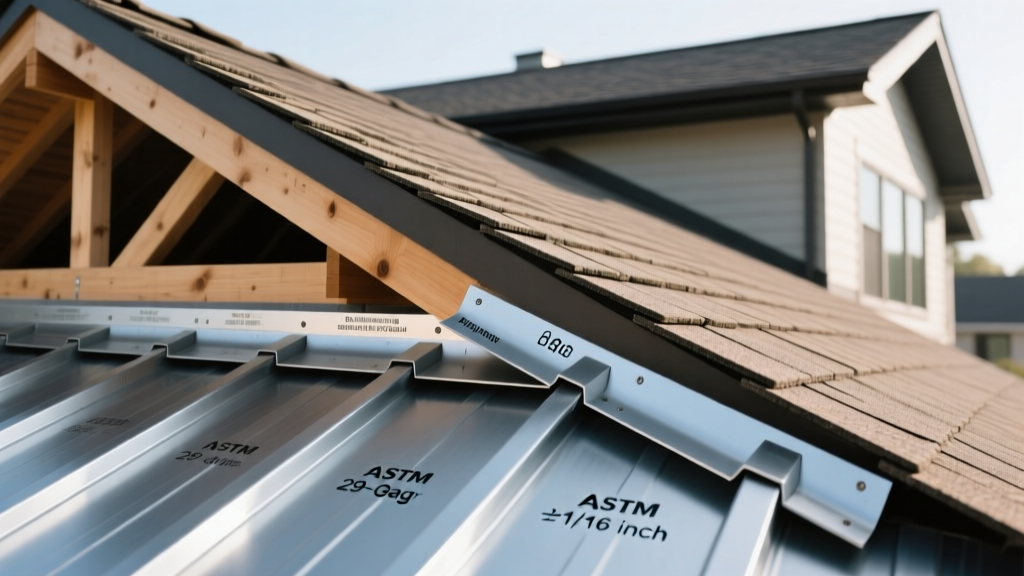
Material Specifications and Gauge Requirements
The structural integrity of a step flashing roof transition relies entirely on the metallurgical properties and gauge thickness of the flashing material. When specifying materials for roof-to-wall intersections, contractors must adhere to strict ASTM standards to prevent premature degradation from thermal cycling, UV exposure, and galvanic corrosion. The three primary materials utilized in modern step flashing systems are copper, aluminum, and galvanized steel, each with distinct performance thresholds.
Copper Flashing (ASTM B370)
Copper remains the premium benchmark for step flashing due to its exceptional longevity and natural patina formation, which acts as a protective oxide layer. For step flashing applications, 16-ounce copper (0.0216 inches thick) is the absolute minimum acceptable specification, though 20-ounce copper (0.027 inches thick) is strongly recommended for high-wind zones or regions with severe thermal fluctuation. Copper exhibits a thermal expansion coefficient of 9.4 x 10^-6 in/in/°F, requiring careful allowance for movement in long continuous runs, though step flashing's segmented nature naturally mitigates this stress.
Aluminum Flashing (ASTM B209)
Aluminum is highly resistant to atmospheric corrosion but is vulnerable to alkaline environments. The minimum thickness for aluminum step flashing is 0.019 inches, but 0.024 inches is the industry-preferred standard to resist bending during installation and wind-driven debris impact. Crucial specification note: Aluminum must never be used in direct contact with untreated cedar, redwood, or fresh masonry, as the tannins and alkalinity will cause rapid chemical pitting and perforation within 3 to 5 years.
Galvanized Steel (ASTM A653)
For budget-conscious projects, galvanized steel is acceptable provided it meets the G90 zinc coating classification (0.90 oz/sq ft total zinc weight). The minimum gauge requirement is 26-gauge (0.0179 inches), but 24-gauge is vastly superior for resisting mechanical damage from foot traffic during subsequent roof maintenance. The G90 coating provides approximately 1,000 hours of salt spray resistance before red rust emerges, making it unsuitable for coastal environments within 1,500 feet of the surf zone.
Never mix dissimilar metals in a step flashing roof assembly. If copper step flashing is installed above aluminum gutters or alongside galvanized steel drip edges, the copper ions washing down the roof plane will induce catastrophic galvanic corrosion in the less noble metals. Always isolate dissimilar metals using butyl rubber separation tape or specify uniform metallurgy across the entire drainage path.
Dimensional Standards and Headlap Tolerances
The physical dimensions of step flashing dictate its ability to shed water and integrate with the primary roof covering. The National Roofing Contractors Association (NRCA) and the Sheet Metal and Air Conditioning Contractors' National Association (SMACNA) outline precise dimensional tolerances that must be met for warranty compliance.
- Standard Dimensions: The baseline specification is a 7-inch by 7-inch piece, bent at a 90-degree angle to create two 5-inch flanges (accounting for the bend radius). This provides adequate coverage for standard 5-inch exposure asphalt shingles.
- High-Wind/Heavy-Snow Dimensions: In regions governed by strict 2024/2025 IBC wind uplift codes or heavy snow load zones, 8-inch by 8-inch step flashing is mandated. This wider profile accommodates the larger 7-inch to 8-inch exposure profiles of architectural shingles and slate.
- Kick-Out Requirement: The bottom edge of the vertical flange must feature a minimum 1/2-inch outward 'kick-out' or hem to direct water away from the vertical wall and prevent capillary draw back into the masonry or siding joint.
- Headlap Tolerances: Each successive piece of step flashing must overlap the piece below it by a minimum of 2 inches. For roof pitches below 4:12, this headlap must be increased to 3 inches to counteract the slower water velocity and higher risk of capillary action.
Step Flashing Material Performance Matrix
The following table synthesizes the core performance specifications required for procurement and quality assurance inspections on commercial and high-end residential projects.
| Material | ASTM Standard | Min. Thickness | Salt Spray (Hrs) | Thermal Expansion |
|---|---|---|---|---|
| Copper (20 oz) | ASTM B370 | 0.0270' | N/A (Patina) | 9.4 x 10^-6 |
| Aluminum | ASTM B209 | 0.0240' | 1,500+ | 13.1 x 10^-6 |
| Galv. Steel (G90) | ASTM A653 | 0.0179' (26ga) | 1,000 | 6.5 x 10^-6 |
| Lead-Coated Copper | ASTM B101 | 0.0250' | 2,000+ | 9.4 x 10^-6 |
Wind Uplift and Integration Ratings
The performance of a step flashing roof system during extreme weather events is dictated not just by the metal, but by its integration with the roof covering. According to NRCA guidelines, step flashing must be woven into the shingle courses, never installed in a continuous surface-mount strip.
Shingle Woven Integration vs. Surface Mount
Surface-mounted continuous flashing (often erroneously sold as 'step flashing' in big-box stores) fails under wind uplift because it relies entirely on sealant and surface friction. True step flashing is individually layered under each shingle. When wind uplift forces (tested per ASTM D7158) pull the shingle upward, the step flashing moves in unison with the shingle, maintaining the water barrier. Continuous flashing creates a hinge point that tears under Class F (110 mph) or Class H (150 mph) wind uplift ratings.
'The primary failure mechanism in roof-to-wall intersections is not the metal failing, but the hydrostatic pressure of wind-driven rain bypassing continuous flashing. Step flashing segments the water flow, reducing hydrostatic load by up to 85% compared to continuous J-channel methods.' — Derived from SMACNA Architectural Sheet Metal Manual principles.
Fastening Protocols and Structural Isolation
A critical, frequently misunderstood specification in step flashing roof installation is the fastening protocol. Step flashing must never be fastened to the vertical wall. It should only be secured to the roof deck, or in premium installations, left entirely unfastened ('floating') and held in place solely by the weight and fasteners of the overlying shingle.
If step flashing is nailed to the vertical sidewall, the differential movement between the roof truss (which deflects under snow loads) and the vertical wall (which remains static) will shear the nails or tear the metal within 3 to 5 thermal cycles. Furthermore, penetrating the vertical wall's weather-resistive barrier (WRB) with flashing nails creates a direct vector for water intrusion. The correct specification requires one roofing nail per step flashing piece, driven into the roof deck only, positioned high enough to be covered by the overlapping shingle's nail line.
Environmental Degradation and Failure Thresholds
Understanding the specific failure modes of step flashing allows for better material selection based on micro-climates. The following edge cases dictate material upgrades:
- Acid Rain and Industrial Zones: In areas with high sulfur dioxide emissions, galvanized steel zinc coatings degrade at an accelerated rate of 1.5 to 2.0 microns per year. In these zones, specify 20 oz copper or heavy-gauge aluminum with a Kynar 500 PVDF factory-applied coating.
- Coastal Salt Spray: Within a 3-mile radius of ocean coastlines, standard G90 galvanized steel will exhibit white rust within 6 months and red rust within 24 months. ASTM standards dictate the use of aluminum or copper for coastal step flashing, as aluminum forms a self-healing aluminum oxide layer that resists chloride ion penetration.
- Ice Dam Prone Valleys: In climates with prolonged sub-freezing temperatures, meltwater can back up under the shingles. Step flashing in these zones must be integrated with a minimum 36-inch wide self-adhering polymer-modified bitumen ice and water shield membrane that extends up the vertical wall a minimum of 8 inches above the interior ceiling line.
Sourcing and Procurement Specifications
When drafting procurement documents or evaluating subcontractor submittals, require mill certificates for copper and aluminum flashing to verify alloy composition. For copper, ensure it is Cold Rolled (H00 or H01 temper) rather than soft annealed copper, as annealed copper lacks the rigidity to maintain its 90-degree bend under the weight of snow and ice. For aluminum, specify alloy 3003-H14, which offers the optimal balance of formability and tensile strength for the tight bends required in step flashing fabrication. By enforcing these exact SMACNA and NRCA technical specifications, building owners can ensure the step flashing roof transition outlasts the primary roof covering itself.