Stone Veneer Front of House: Technical Specs and Load Limits
Master the technical specs for stone veneer front of house projects. Explore load limits, ASTM standards, moisture management, and framing requirements.

Structural Load Capacity and Framing Deflection Limits
When engineering a stone veneer front of house installation, the primary structural constraint is the dead load imposed on the wall assembly and the resulting deflection limits. The International Residential Code (IRC Section R703.7) and International Building Code (IBC Chapter 14) dictate strict parameters for adhered masonry veneers to prevent catastrophic delamination or mortar fracturing.
Dead Load Calculations
- Manufactured Stone Veneer (MSV): Typically weighs between 10 and 15 pounds per square foot (psf). Standard 2x4 wood framing at 16 inches on-center (OC) is generally sufficient to support this load without supplemental structural reinforcement.
- Natural Stone Veneer: Ranges from 25 to over 40 psf depending on the geology (e.g., granite vs. limestone) and cut thickness. Natural stone applications frequently require 2x6 wood framing, 16-inch OC spacing, or heavy-gauge (16-gauge minimum) steel studs to safely transfer the load to the foundation.
Deflection Criteria
Brittle cladding systems, including all Portland cement-based scratch coats and adhered stone, require a strict deflection limit of L/600 under live and wind loads. If a wall assembly is designed only to the standard L/360 deflection limit, the flexing of the studs during high-wind events will crack the scratch coat, breaking the mechanical bond between the lath and the stone. For multi-story front elevations, structural engineers must calculate cumulative lateral drift to ensure the L/600 threshold is maintained across the entire facade.
Moisture Management and Weather-Resistive Barriers (WRB)
Bulk water intrusion is the leading cause of adhered veneer failure. Because stone and mortar are highly porous, a stone veneer front of house acts as a reservoir cladding system. It absorbs rainwater and holds it against the wall assembly, necessitating a robust drainage plane behind the scratch coat.
WRB Configuration Requirements
According to building science principles outlined by the Building Science Corporation, a single layer of housewrap is insufficient for reservoir claddings. The code-compliant and technically sound specification requires:
- Inner Layer: A continuous, code-approved water-resistive barrier (e.g., spunbonded polyolefin housewrap) taped at all seams to act as the primary air and water barrier.
- Outer Layer: Grade D building paper (ASTM D226, 60-minute rating) or a specialized textured drainage mat. This sacrificial layer bonds to the mortar scratch coat while allowing incidental moisture to drain downward.
Weep Screed and Flashing Specifications
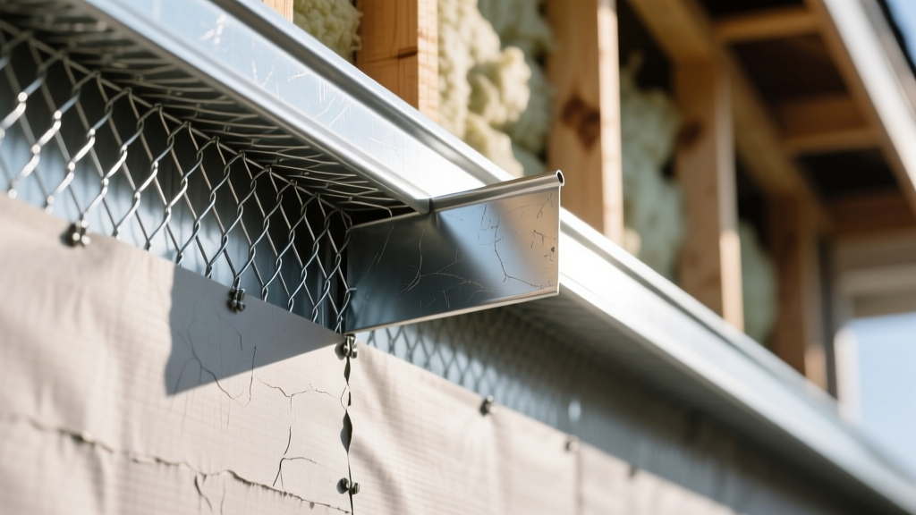
The termination point of the veneer is its most vulnerable junction. A corrosion-resistant weep screed (minimum 3.5-inch vertical flange, complying with ASTM C932) must be installed at the base of the wall. The WRB must lap over the vertical flange of the weep screed by at least 2 inches to ensure water is directed outward. Furthermore, maintain a strict minimum clearance of 4 inches above exposed earth and 2 inches above paved surfaces to prevent capillary action and splash-back degradation.
ASTM Standards and Material Compliance Matrix
Specifying materials without referencing standardized testing protocols invites liability and premature failure. The Masonry Veneer Manufacturers Association (MVMA) mandates strict adherence to the following ASTM standards for all manufactured and adhered stone products.
| ASTM Standard | Material / Process | Key Performance Metric |
|---|---|---|
| ASTM C1670 | Manufactured Stone Veneer (MSV) | Freeze-thaw durability, compressive strength, and water absorption limits. |
| ASTM C1892 | MSV Installation Practices | Mortar coverage, jointing techniques, and substrate preparation. |
| ASTM C926 | Portland Cement Plaster (Scratch Coat) | Thickness tolerances, curing times, and mix proportioning. |
| ASTM C1063 | Lath and Furring | Wire mesh weight, furring stand-off distances, and fastening schedules. |
| ASTM A1064 | Carbon-Steel Wire Mesh | Galvanization coating thickness and tensile strength of the wire. |
Lath Fastening and Mortar Mix Proportions
The mechanical connection between the structural framing and the stone veneer relies entirely on the lath and the chemical bond of the mortar. Cutting corners on fastener schedules or mortar ratios is a primary driver of warranty claims.
Wire Mesh and Fastening Schedule
Specify 2.5 lb/sq yd self-furring galvanized welded wire mesh (ASTM A1064). The self-furring dimples must hold the mesh exactly 1/4 inch away from the WRB, allowing the scratch coat to fully encapsulate the wire. Fasten the mesh using 1-1/2 inch galvanized roofing nails or staples with 1/4 inch stand-off crowns. The fastening schedule must be 6 inches OC vertically and 16 inches OC horizontally, penetrating directly into the structural framing studs, not just the OSB or plywood sheathing.
Mortar Specification: Type S vs. Type N
Always specify Type S mortar for both the scratch coat and the setting bed on exterior stone veneer front of house projects. Type S offers a minimum compressive strength of 1,800 psi and significantly higher flexural bond strength compared to Type N (750 psi), which is critical for resisting wind shear and thermal expansion.
- Type S Mix Ratio: 1 part Portland cement (ASTM C150), 1/2 part hydrated lime (ASTM C206), and 4.5 parts damp, loose masonry sand (ASTM C144).
- Scratch Coat Application: Apply at a minimum thickness of 3/8 inch. Horizontally score the surface with a 1/8 inch deep rake while the mortar is thumb-print hard. Cure for a minimum of 24 to 48 hours, keeping the surface damp to prevent plastic shrinkage cracking.
Expansion Joints and Thermal Movement
Stone and mortar expand and contract at different rates than wood and steel framing. Without properly specified control joints, the veneer will relieve thermal stress through uncontrolled, jagged cracking. Control joints must be installed in a continuous grid pattern, breaking the veneer into manageable panels.
Install vertical control joints every 18 feet horizontally, and horizontal control joints every 12 feet vertically. All control joints must align directly with structural expansion joints in the underlying framing and sheathing. Use a closed-cell polyethylene backer rod and a high-modulus polyurethane sealant (ASTM C920) to seal the joint, allowing for +/- 25% joint movement.
Troubleshooting Common Specification Failures
When a stone veneer front of house exhibits distress, the root cause is almost always traceable to a deviation from the technical specifications outlined above. Use this diagnostic framework to identify and rectify field failures.
1. Severe Efflorescence and Mineral Staining
Symptom: White, powdery deposits on the stone face or mortar joints shortly after installation.
Technical Cause: Soluble salts within the Portland cement are being dissolved by bulk water moving through the wall assembly and deposited on the surface as the water evaporates. This indicates a failure in the WRB drainage plane or missing weep screeds trapping water behind the lath.
Remediation: Dry-brush the deposits. Do not use acid washes on MSV, as it degrades the cementitious matrix. Address the bulk water intrusion source at the roofline or window flashing immediately.
2. Map Cracking in the Scratch Coat
Symptom: A web-like pattern of fine cracks visible through the mortar joints or causing stones to pop loose.
Technical Cause: Rapid moisture loss during the curing phase (plastic shrinkage) or an overly rich mortar mix (too much cement, not enough sand). It can also result from framing deflection exceeding the L/600 limit.
Remediation: If the mesh is still fully encapsulated and bonded to the sheathing, the scratch coat can be re-scored and a secondary bonding agent applied before setting the stone. If the lath has detached, the entire section must be demolished and re-furred.
3. Delamination at the Top Course
Symptom: Stones pulling away from the wall near the soffit or roofline.
Technical Cause: Lack of a horizontal control joint at the floor-to-wall intersection, or missing Z-flashing above the veneer cap allowing driven rain to saturate the top edge of the scratch coat.
Remediation: Install a continuous Z-flashing at the top termination, integrating it with the primary WRB, and ensure a 1/2 inch clearance between the top of the stone and the soffit, sealed with a compressible backer rod and elastomeric sealant.
Written by
Marcus ChenMarcus Chen is a licensed structural engineer (PE) and building materials analyst with over 12 years of experience across residential, commercial, and industrial construction. He holds a Master of Science in Civil Engineering from UC Berkeley and spent six years at Thornton Tomasetti before transitioning to independent consulting and technical writing. Marcus specializes in material selection for seismic-prone regions, concrete reinforcement strategies, and lifecycle cost analysis. His work has been cited by the American Concrete Institute (ACI) and the Structural Engineers Association of California (SEAOC). When he is not on a job site or at his desk, you will find him hiking the Sierra Nevada or restoring a 1920s craftsman bungalow in Oakland, CA.
More from Marcus Chen
View all
Construction Cost
How Much Did the Eiffel Tower Cost to Build?
How much did the Eiffel Tower cost to build in 1889? We adjust for inflation and compare its budget to modern skyscraper construction.
Aug 4, 2026

Fire Resistance
What Is a Fire Resistant Material? Testing & Certification Guide
Discover what is a fire resistant material through ASTM and UL testing. Learn how fire ratings, certifications, and assemblies work in construction.
Aug 4, 2026

Construction Cost
How Much Did the Burj Khalifa Cost to Build?
How much did the Burj Khalifa cost to build? We break down the $1.5B project and extract 5 money-saving strategies for your next build.
Jul 30, 2026