How to Frame Load-Bearing Walls Using 2x6 Lumber: Installation Guide
Master load-bearing wall installation with 2x6 lumber. Learn advanced framing steps, 24-inch O.C. spacing, fastener schedules, and current code specs.
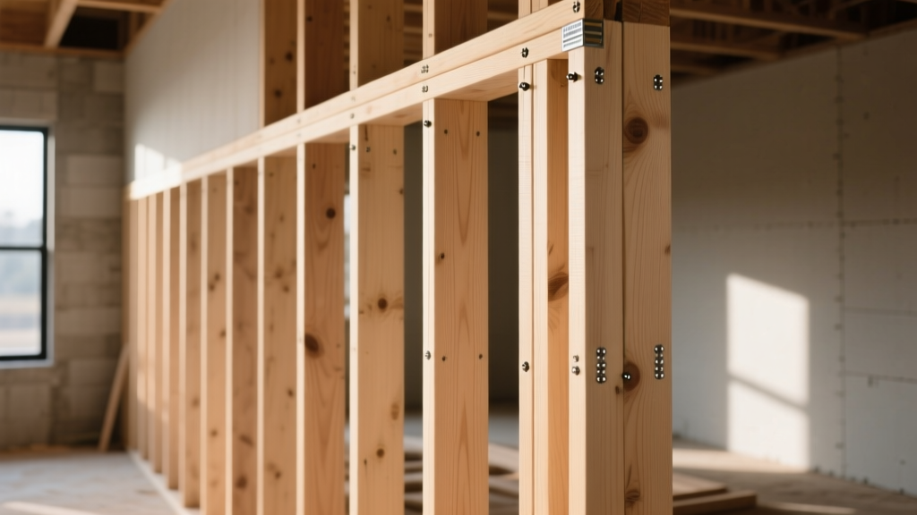
The Structural Advantage of 2x6 Lumber in Load-Bearing Walls
Transitioning from standard 2x4 to 2x6 lumber for exterior load-bearing walls fundamentally alters a building's structural capacity and thermal envelope. A true 2x6 stud provides a 5.5-inch cavity, accommodating R-20 to R-30 batt insulation or dense-pack cellulose, which is increasingly mandated by the 2024 and 2026 International Energy Conservation Code (IECC) cycles for climate zones 4 and higher. Beyond insulation, the 5.5-inch depth increases the wall's moment of inertia, drastically improving resistance to wind shear and allowing for wider stud spacing under advanced framing protocols.
Material Selection: Grade Stamps and Moisture Metrics
Not all 2x6 lumber is interchangeable for load-bearing applications. Inspect the grade stamp on every stud before installation. For standard residential load-bearing walls, SPF (Spruce-Pine-Fir) #2 is the baseline acceptable grade. For high-load applications, such as supporting heavy roof trusses or multi-story point loads, specify Douglas Fir-Larch (DF-L) #2 or better, which offers roughly 25% higher bending (Fb) and compression (Fc) values.
Moisture content (MC) is the most frequently overlooked installation variable. Lumber must be stamped S-DRY (Surface Dry, meaning MC ≤ 19%) or KD (Kiln Dried, MC ≤ 15%). Installing green or S-GRN (Surface Green) 2x6 studs in interior or enclosed exterior walls guarantees severe twisting, nail popping, and drywall cracking as the wood equilibrates to the conditioned space's 8-12% MC.
Step-by-Step Installation Procedure
Step 1: Subfloor Prep and Plate Layout
Before snapping chalk lines, install a capillary break between the concrete foundation and the pressure-treated bottom plate. Use a 1/4-inch closed-cell sill sealer foam or a fluid-applied asphalt emulsion. Never place untreated 2x6 lumber directly on concrete, and never use pressure-treated lumber for the top plates or internal studs, as the copper-based preservatives (like ACQ or MCQ) will corrode standard fasteners and complicate drywall finishing.
When laying out the 16-inch or 24-inch on-center (O.C.) spacing on the top and bottom plates, shift your pencil mark 3/4 of an inch from the exact 16" or 24" tick. This offset accounts for the 1.5-inch thickness of the stud, ensuring the leading edge of the 2x6 falls exactly on the modular dimension. This is non-negotiable for ensuring the edges of 4x8 OSB sheathing and drywall land perfectly on the center of a stud.
Step 2: Stud Placement and Crown Alignment
Every piece of 2x6 lumber has a natural "crown" (a slight bow along its narrow edge). Stand the stud on its edge and sight down the narrow 1.5-inch face. Mark the high point of the crown with an arrow. During installation, orient all crowns in the exact same direction (typically facing outward toward the exterior sheathing). If crowns are alternated, the wall will have a wavy profile that no amount of drywall taping can hide.
Step 3: Fastening and Assembly
Assemble the wall flat on the subfloor. End-nail the 2x6 studs through the top and bottom plates. For production speed and structural rigidity, pneumatic framing nailers driving 16d common nails are standard, but structural screws are increasingly preferred for their superior withdrawal resistance and lack of vibration-induced micro-fractures in the wood.
| Joint Type | Pneumatic Nail Requirement | Structural Screw Alternative |
|---|---|---|
| Stud to Plate (End Nail) | Two 16d common (3.5" x 0.162") | Two 3.5" structural screws (e.g., Simpson SDWS) |
| Double Top Plate Splice | Eight 16d nails staggered over 48" | Six 3.5" structural screws staggered |
| Blocking to Stud (Face Nail) | Two 16d common nails per end | Two 3.0" structural screws per end |
| Bottom Plate to Concrete Sill | 1/2" x 6" wedge anchors @ 48" O.C. | 1/4" x 3-3/4" concrete screws @ 32" O.C. |
Advanced Framing Techniques (24" O.C. Optimization)
According to the U.S. Department of Energy's advanced framing guidelines, spacing 2x6 studs at 24 inches O.C. rather than 16 inches O.C. reduces lumber usage by up to 30% while increasing the cavity space for insulation, effectively eliminating thermal bridging through the studs. To execute this legally and safely, you must adopt the following advanced framing details:
- Single Top Plates: Because the studs align directly under the roof trusses or floor joists (which are also spaced 24" O.C.), a single 2x6 top plate is sufficient. This requires the use of approved structural steel truss plates or ties to connect the truss to the single top plate.
- Ladder Blocking at Intersections: Instead of traditional three-stud corners or partition intersecting posts that create massive cold spots, use horizontal "ladder" blocking between the last two studs. This maintains the structural tie-in while allowing insulation to wrap continuously around the corner.
- Right-Sized Headers: In 2x6 walls, headers should be sized precisely for the load and span, rather than defaulting to oversized 2x12s. For many single-story residential window spans, a 2-ply 2x8 or 2-ply 2x10 header with a 1/2-inch rigid foam spacer is sufficient, leaving room for cavity insulation above the window.
Raising, Plumbing, and Bracing
Once the wall is fully assembled and sheathed with 7/16-inch OSB or 1/2-inch plywood (applying the required nailing pattern for shear walls, typically 6d nails at 6" O.C. on edges and 12" O.C. in the field), raise the wall using hydraulic wall jacks or a coordinated crew lift.
Immediately secure the bottom plate with temporary diagonal braces. Use a 78-inch digital level to plumb the wall. Pro-Tip: Do not just check the center of the wall; check the corners and the mid-span. A 2x6 wall can bow in the center even if the corners are plumb. Adjust the turnbuckles on your diagonal braces until the wall is perfectly plumb within a 1/8-inch tolerance over 8 feet, then permanently anchor the bottom plate to the subfloor framing using 16d nails or structural screws driven at a 45-degree angle (toenailing) if direct access is blocked.
Common Installation Failures to Avoid
- Ignoring the Rim Joist Alignment: When stacking a second-floor 2x6 wall, the bottom plate must sit directly over the floor joists or rim joist below. If the wall is offset onto the OSB subfloor alone, the point load will crush the subfloor and cause severe sagging.
- Improper Sill Sealer Compression: If using foam sill seal, ensure it is compressed by the weight of the wall and the tightened anchor bolts. Uncompressed foam leaves a 1/4-inch air gap that compromises the building's blower-door test results and allows bulk water intrusion during wind-driven rain events.
- Mixing Lumber Species in a Single Load Path: Do not mix SPF and DF-L studs in the same load-bearing wall line. The differential shrinkage rates and stiffness moduli (E) will cause uneven load distribution, potentially overloading the stiffer DF-L studs while the SPF studs shrink and lose bearing contact with the top plate.
Precision in 2x6 load-bearing wall installation dictates the long-term structural integrity and energy performance of the structure. By adhering to strict moisture controls, executing modular layout mathematics, and leveraging advanced framing topologies, builders can maximize both the ROI and the durability of the building envelope.