Pouring Concrete Footings: Trenching, Forming, and Curing
Learn the exact procedures for pouring structural concrete footings. Covers frost line trenching, rebar placement, 3000 PSI mix ratios, and curing timelines.
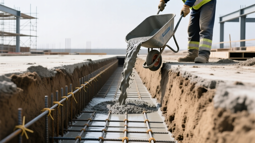
The Physics of Load Transfer: Why Footings Fail
Concrete footings serve as the critical structural interface between a building's vertical loads and the underlying soil. Their primary function is to spread concentrated point loads (from columns) or linear loads (from bearing walls) over a wide enough area to prevent the soil from exceeding its bearing capacity. When footings fail, it is rarely due to the concrete crushing; rather, failure occurs via differential settlement, shear failure of the underlying soil, or frost heave.
A properly engineered and poured footing requires strict adherence to depth, width, and reinforcement specifications. Ignoring the International Building Code (IBC) requirements for frost depth or soil compaction will result in structural cracking that propagates upward through the foundation wall and into the superstructure.
Pre-Pour Preparation: Trenching and Soil Compaction
The IBC mandates that footings must extend a minimum of 12 inches below undisturbed soil. In climates subject to freezing, the bottom of the footing must also rest below the local frost line to prevent frost heave—a phenomenon where freezing soil moisture expands and lifts the foundation unevenly. According to the International Code Council (ICC), soil bearing capacity dictates the required width of the footing.
Presumptive Soil Bearing Capacities
Before pouring, verify your soil type. The following table outlines standard presumptive bearing values used when a geotechnical soil test is not mandated by the local building department:
| Soil Classification | Presumptive Bearing Capacity (psf) | Required Footing Width (for 3,000 lb/lin ft load) |
|---|---|---|
| Bedrock | 12,000 | Minimum code (typically 12 inches) |
| Sandy Gravel / Gravel | 3,000 - 4,000 | 12 to 14 inches |
| Sand / Silty Sand | 2,000 - 3,000 | 16 to 18 inches |
| Clay / Sandy Clay | 1,500 - 2,000 | 20 to 24 inches |
Formwork and Reinforcement Specifications
Footing forms must withstand the immense lateral pressure of wet concrete, which exerts roughly 150 pounds per cubic foot of hydrostatic pressure. Use 2x8 or 2x10 dimensional lumber, staked securely with 2x2 wooden stakes or steel form pins driven into the earth every 24 inches. For curved footings, use 1/4-inch plywood or flexible hardboard.
Rebar Sizing and Placement
Standard residential footings require a minimum of two continuous #4 (1/2-inch diameter) or #5 (5/8-inch diameter) Grade 60 steel reinforcing bars.
- Concrete Cover: Maintain a strict 3-inch clearance between the rebar and the earth on the bottom and sides. This cover protects the steel from moisture-induced corrosion. Never use rocks to prop up rebar; use high-density plastic rebar chairs (dobies) spaced every 4 feet.
- Lap Splices: Where rebar lengths must overlap, the minimum splice length is 40 times the bar diameter. For a #4 bar, this equates to a 20-inch overlap. Secure splices with 16-gauge tie wire at both ends of the overlap.
- Vertical Dowels: If the footing will support a poured concrete wall or CMU block wall, insert vertical #4 or #5 dowels into the wet footing at 48-inch intervals. These must extend into the footing with a 90-degree hook and project upward to tie into the wall's horizontal reinforcement.
The Pour: Mix Designs and Placement Techniques
For standard residential and light commercial footings, a 3,000 PSI (pounds per square inch) compressive strength mix is the baseline requirement. However, in regions with severe freeze-thaw cycles, upgrading to a 4,000 PSI mix with 4% to 6% air-entrainment is critical. The Portland Cement Association (PCA) notes that microscopic air bubbles created by air-entraining admixtures provide essential expansion chambers for freezing water, preventing internal spalling and micro-cracking.
Order your concrete with a 4-inch to 5-inch slump. If the batch arrives too stiff, do not instruct the driver to add water on-site beyond the batch ticket's allowable limit. Adding just 1 gallon of water per cubic yard can reduce the concrete's compressive strength by up to 10% and increase shrinkage cracking. If higher workability is needed for pumping, request a mid-range water-reducing admixture (superplasticizer) at the batch plant.
Vibration and Consolidation
Simply shoveling concrete into forms leaves air pockets that result in 'honeycombing'—voids that expose the rebar and compromise structural integrity. Use a 1-inch to 1.5-inch diameter internal pencil vibrator. Insert the vibrator vertically every 12 to 18 inches along the trench. The rule of thumb is to vibrate for roughly 1 second per inch of slump (e.g., 4 to 5 seconds). You will know consolidation is complete when a thin layer of paste (fines) rises to the surface and large air bubbles cease to escape.
Curing Protocols and Stripping Forms
Concrete does not 'dry'; it cures through a chemical hydration process that requires moisture. If the surface dries out too quickly, plastic shrinkage cracks will form within hours. Immediately after screeding and finishing the top surface, apply a liquid membrane-forming curing compound or cover the footing with wet burlap and 4-mil polyethylene sheeting.
Maintain this moist curing environment for a minimum of 7 days for standard Portland cement mixes, or 3 days if using Type III (high-early-strength) cement. Forms can typically be stripped after 24 to 48 hours, provided the concrete has achieved sufficient strength to resist chipping at the edges. Backfill the trench only after the forms are removed and the curing compound has fully set.
Troubleshooting Common Footing Defects
Even with meticulous planning, field conditions can introduce defects. Use the following diagnostic matrix to identify and remediate common footing issues before proceeding with foundation wall construction.
| Defect | Root Cause | Structural Remediation |
|---|---|---|
| Honeycombing (exposed aggregate/voids on sides) | Insufficient vibration, overly stiff mix, or rebar placed too close to forms blocking aggregate flow. | Chip away loose material, clean with a wire brush, and patch with a high-strength, non-shrink polymer-modified structural grout. |
| Cold Joints (weak horizontal planes) | Delay in concrete delivery causing the first batch to begin setting before the second batch was placed. | If the joint is structural, consult an engineer. May require epoxy injection or supplemental steel doweling across the joint line. |
| Surface Scaling (flaking top layer) | Troweling bleed water back into the surface, or inadequate air-entrainment in freeze-thaw climates. | Grind off the scaled surface and apply a penetrating silane/siloxane water repellent to prevent further moisture ingress. |
For comprehensive details on residential foundation design and moisture management, refer to the HUD Residential Foundations Guidelines, which provide extensive data on load paths and drainage integration for concrete footing systems.