Floor Heating Systems Specs: Wattage, BTU & Efficiency Ratings
Compare floor heating systems by performance ratings. Learn exact wattage, BTU outputs, R-value limits, and efficiency specs for hydronic and electric mats.
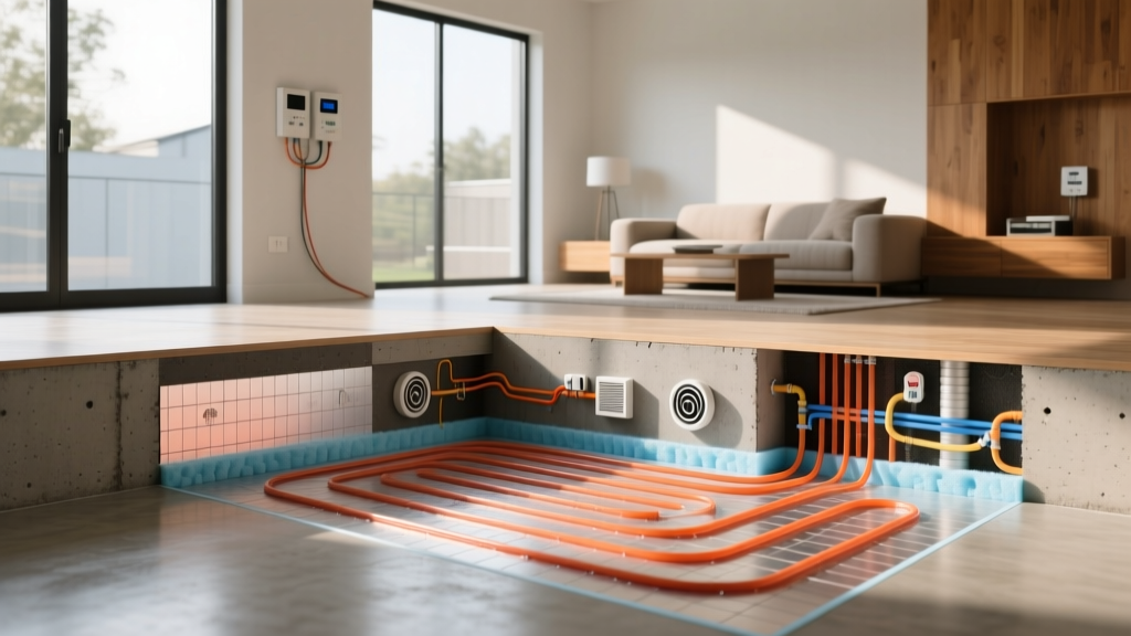
Decoding Floor Heating Systems Performance Metrics
Selecting between radiant heating technologies requires moving beyond basic marketing claims to analyze hard thermal engineering data. In 2026, with updated International Energy Conservation Code (IECC) mandates and the widespread adoption of low-temperature air-to-water heat pumps, the performance specifications of floor heating systems dictate not just comfort, but overall building energy efficiency. Whether evaluating electric resistance cables or hydronic PEX tubing loops, installers and architects must align system output (Wattage or BTU/hr) with the specific heat loss profile of the structure and the thermal resistance (R-value) of the chosen floor covering.
Electric vs. Hydronic: Core Output Specifications
The fundamental divergence in floor heating systems lies in how thermal energy is generated and distributed. Electric systems rely on resistive wire elements, while hydronic systems circulate heated fluid through a network of tubes. The table below outlines the baseline performance envelopes for both technologies in standard residential applications.
| Specification Metric | Electric Mat/Cable Systems | Hydronic PEX Tube Systems |
|---|---|---|
| Standard Output Density | 12W to 15W per sq. ft. | 20 to 35 BTU/hr per sq. ft. |
| Maximum Floor Surface Temp | 85°F (29.4°C) per UL/CSA limits | 85°F (29.4°C) for wood; 95°F for tile |
| Thermal Response Time | 30 to 60 minutes (thinset embedment) | 2 to 6 hours (gypsum/concrete embedment) |
| Operating Voltage / Pressure | 120V or 240V AC | 12 to 30 PSI (closed loop) |
| Ideal Application Scale | Supplemental heat, single rooms, retrofits | Whole-home primary heating, new construction |
Electric Cable and Mat Wattage Density
Electric floor heating systems are manufactured in specific wattage densities, dictated by the spacing of the resistive wire. The most common residential specification is 12 watts per square foot, which yields approximately 41 BTU/hr per square foot. This is sufficient for well-insulated rooms where the system acts as a supplemental comfort layer.
For spaces with higher heat loss—such as sunrooms, bathrooms with extensive exterior glass, or rooms built over unconditioned crawlspaces—15-watt systems (yielding ~51 BTU/hr/sq. ft.) are required. These achieve higher output by reducing the cable spacing from 4 inches down to 3 inches.
Hydronic Tube Spacing and Flow Dynamics
Hydronic floor heating systems performance is governed by tube diameter, spacing, and fluid flow rate (GPM). Modern systems predominantly use 1/2-inch PEX-a (cross-linked polyethylene) with an EVOH oxygen diffusion barrier to prevent boiler corrosion.
- 6-inch Spacing: Yields ~35 BTU/hr/sq. ft. Reserved for high-load areas, slab-on-grade perimeters, or snowmelt applications.
- 9-inch Spacing: Yields ~25 BTU/hr/sq. ft. The standard for most residential living spaces over wood subfloors using pour-over gypsum underlayments.
- 12-inch Spacing: Yields ~18 BTU/hr/sq. ft. Used in low-load environments, such as highly insulated basements or interior hallways.
According to the U.S. Department of Energy's radiant heating guidelines, modern condensing boilers and air-to-water heat pairs operate most efficiently when supplying water temperatures between 85°F and 110°F. To maintain this low Delta-T (ΔT) while meeting BTU demands, hydronic loops must be designed with precise flow rates, typically targeting 0.5 to 1.0 GPM per circuit.
The R-Value Bottleneck: Flooring Material Limitations
The most common cause of floor heating systems failure is not a defective wire or a leaking pipe, but the installation of a floor covering with an excessively high thermal resistance (R-value). Floor coverings act as insulators; if the R-value is too high, the heat cannot penetrate into the room. This causes the heating element to overheat, potentially tripping thermal cutoffs, degrading the wire insulation, or delaminating engineered wood.
Industry standards, including those published by the National Wood Flooring Association (NWFA), strictly mandate that the combined R-value of the floor covering and any underlayment must not exceed specific thresholds.
| Flooring Material | Typical R-Value | Radiant Heat Compatibility | Installation Notes |
|---|---|---|---|
| Porcelain / Ceramic Tile | 0.05 - 0.10 | Excellent (Ideal) | Use unmodified or specific polymer-modified thinset. Uncoupling membranes like Schluter Ditra-Heat are highly recommended to prevent cracking. |
| Natural Stone (Marble, Slate) | 0.05 - 0.15 | Excellent | Requires 100% mortar coverage to prevent voids that cause thermal stress fractures. |
| Luxury Vinyl Plank (LVP) | 0.20 - 0.40 | Good (Check Manufacturer) | Floor surface temp must not exceed 85°F. Glue-down LVP transfers heat better than floating LVP. |
| Engineered Hardwood | 0.25 - 0.60 | Good (With Restrictions) | Must be quartersawn or rift-sawn. Plank width should not exceed 4 inches to minimize cupping. |
| Solid Hardwood | 0.60 - 1.00 | Poor (High Risk) | Highly susceptible to seasonal gapping and checking. Generally not warranted by manufacturers over radiant heat. |
| Carpet with Foam Pad | 1.50 - 2.50+ | Not Recommended | Blocks thermal transfer entirely. If used, pad must be low-density rubber (R-value < 0.5). |
Control Systems: Modulation and Safety Specs
The thermostat is the brain of the floor heating system. In 2026, basic relay-based thermostats are being replaced by Pulse Width Modulation (PWM) and solid-state controls, particularly for hydronic mixing valves and high-end electric mats.
GFCI and Ground Fault Protection
All electric floor heating systems installed in wet areas (bathrooms, kitchens, mudrooms) require a Class A Ground Fault Circuit Interrupter (GFCI). A Class A GFCI is engineered to trip the circuit when it detects a ground fault current of 5 milliamps (± 1mA). This is a critical safety specification; standard equipment ground fault protection (which trips at 30mA) is insufficient for human safety in wet environments and violates NEC Article 424.44 for embedded heating cables.
Floor Sensor vs. Ambient Sensor Logic
Dual-sensor thermostats are the industry standard. The ambient air sensor regulates the room temperature, while the floor sensor acts as a high-limit safety override. For wood flooring applications, the floor sensor must be hard-coded to a maximum limit of 80°F to 85°F (depending on the wood manufacturer's warranty) to prevent the wood from drying out and cracking, regardless of what the ambient room thermostat demands.
Sizing Framework: Calculating Heat Loss vs. System Output
To ensure a floor heating system can act as a primary heat source, its output must exceed the room's design heat loss. Follow this calculation framework:
- Perform a Room-by-Room Heat Loss Calculation: Use Manual J or equivalent software to determine the BTU/hr heat loss at the local winter design temperature (e.g., 0°F outside, 70°F inside).
- Calculate Available Floor Area: Subtract fixed cabinetry, vanities, and heavy appliances from the total square footage. Heating elements should never be installed under permanent fixtures where heat cannot dissipate.
- Determine Required Output Density: Divide the total BTU/hr heat loss by the available heated square footage.
Example: A bathroom loses 3,000 BTU/hr. Available floor area is 80 sq. ft. Required output = 37.5 BTU/hr/sq. ft. - Select the Technology: In the example above, an electric mat (max ~51 BTU/hr/sq. ft.) can handle the load. If the required output exceeded 55 BTU/hr/sq. ft., floor heating alone would be insufficient, and supplementary forced-air or panel radiators would be required to prevent the floor from exceeding the 85°F safety limit.
Industry Standards and Testing Certifications
When specifying materials, verify that the products carry the appropriate testing certifications. Electric heating cables must be UL listed (Underwriters Laboratories) under UL 1025 or CSA certified under CSA C22.2 No. 46. For hydronic systems, PEX tubing must meet ASTM F876 and ASTM F877 standards for dimensional stability and burst pressure at elevated temperatures. Adhering strictly to these performance ratings ensures system longevity, maintains manufacturer warranties, and guarantees compliance with local building inspections.