When to Specify Floor Trusses: Span, Load, and MEP Routing
Compare floor trusses, I-joists, and dimensional lumber. Learn how to match framing systems to span requirements, MEP routing, and load capacities.
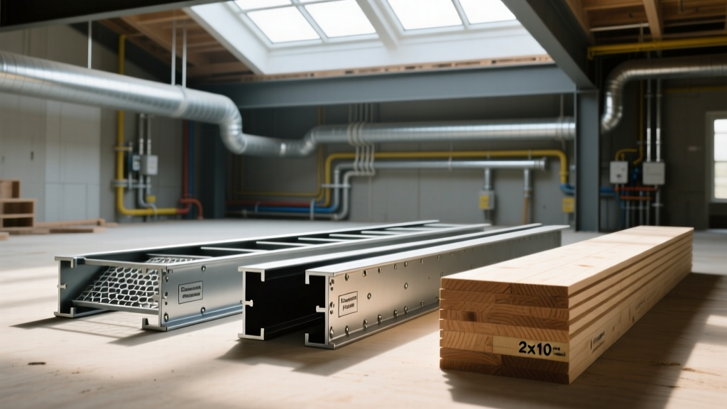
Selecting the right structural floor framing system dictates not only the structural integrity of a building but also the flexibility of its interior layout and the ease of mechanical integration. While dimensional lumber and I-joists dominate standard residential construction, open-web floor trusses solve complex engineering challenges that solid-web systems simply cannot handle. Understanding when to specify floor trusses requires a precise evaluation of clear-span requirements, mechanical, electrical, and plumbing (MEP) density, and strict deflection limits.
The Structural Hierarchy: Floor Trusses vs. Alternatives
Before matching a system to a scenario, builders must understand the physical and economic boundaries of the three primary floor framing systems. The following matrix outlines the operational limits and 2026 market realities for each system.
| Framing System | Max Practical Span | Typical Depth | Est. 2026 Cost (per LF) | MEP Routing Flexibility |
|---|---|---|---|---|
| Dimensional Lumber (2x10/2x12) | 14' - 18' | 9.25" - 11.25" | $1.80 - $2.50 | Very Low (Requires drilling/notching) |
| Engineered Wood I-Joists | 22' - 26' | 9.5" - 16" | $2.50 - $4.20 | Moderate (Pre-stamped knockouts only) |
| Open-Web Floor Trusses | 30' - 45'+ | 16" - 24" | $4.50 - $7.50 | Very High (Large webs for ducts/pipes) |
While floor trusses carry a higher upfront material cost, they frequently reduce total project costs in custom or commercial builds by eliminating the need for intermediate load-bearing walls, reducing foundation point loads, and minimizing HVAC fabrication time.
Scenario Matching: When Floor Trusses Win
Scenario A: Uninterrupted Open Spans (28 to 40+ Feet)
When architectural designs call for massive open-concept living areas, great rooms, or commercial retail spaces without intermediate support columns, floor trusses are the default solution. A standard 24-inch deep floor truss, spaced at 24 inches on center (OC), can easily clear-span 36 feet while supporting standard residential live loads (40 PSF) and dead loads (15 PSF). Attempting to achieve this with I-joists would require depths exceeding 16 inches, deeper foundations, and potentially intermediate steel beams, which complicates the structural load path and increases labor costs.
Scenario B: High-Density MEP Routing
The most significant operational advantage of floor trusses is the open triangular webbing. In modern construction, HVAC return air plenums, 3-inch to 4-inch PVC plumbing drain lines, and heavy electrical conduit runs must traverse the floor cavity. According to the APA - The Engineered Wood Association, cutting or enlarging holes in I-joist webs is strictly governed by manufacturer span tables, often limiting hole diameters to 1.5 inches and requiring specific distances from bearing points. Floor trusses, conversely, are designed with specific "chase openings"—engineered gaps in the webbing that allow 6-inch flexible HVAC ducts and large plumbing stacks to pass through without compromising structural integrity or requiring on-site engineering approvals.
Scenario C: Heavy Point Loads and Stone Tile Finishes
Building codes typically mandate a live-load deflection limit of L/360. However, for high-end residential projects featuring large-format natural stone tile or heavy concentrated loads (like cast-iron clawfoot tubs or slate billiard tables), L/360 is insufficient and will result in cracked grout and tile. Specifying floor trusses designed to an L/480 or L/600 deflection limit provides the extreme stiffness required for these unforgiving finishes. The Wood Truss Council of America (WTCA) emphasizes that truss designers can easily adjust web configurations and lumber grades to meet these stringent deflection criteria, a level of customization impossible with off-the-shelf I-joists.
Critical Failure Modes and Site Errors
WARNING: The "Field Cut" Disaster
The most catastrophic error on a job site involving floor trusses is a tradesperson cutting a top or bottom chord to make room for an uncoordinated duct or pipe. Unlike a solid joist where a small notch reduces capacity incrementally, cutting a truss chord instantly alters the fundamental tension and compression geometry of the entire assembly, leading to immediate or progressive structural failure. If a chase opening is missed, the truss must be evaluated and repaired by the original truss engineer using approved steel reinforcement plates—never field-modified by the framing crew.
Another common failure mode is inadequate bridging. Because floor trusses are typically spaced 24 inches OC and feature narrow top chords (often 2x4s laid flat), the subfloor is more prone to localized deflection between trusses. Installers must use continuous lateral bracing (strongbacks) and proper subfloor adhesives to prevent floor squeaks and ensure the OSB or plywood sheathing acts as a unified structural diaphragm.
Navigating Firestopping and Draftstopping Codes
A frequently overlooked aspect of specifying floor trusses is compliance with concealed space fire codes. Because open-web trusses create continuous, unblocked horizontal channels across the entire floor cavity, they violate standard draftstopping requirements designed to prevent the rapid spread of fire and smoke.
Under the International Residential Code (IRC), these open concealed spaces must be separated into areas not exceeding 1,000 square feet using approved draftstopping materials. Builders must factor in the labor and material costs of installing fire-rated gypsum board, mineral wool batts, or specialized netting at regular intervals to break up the web cavities. Failing to coordinate this with the local building inspector during the framing phase can result in costly rework before drywall installation.
2026 Installation and Sequencing Realities
Integrating floor trusses requires precise logistical planning that differs vastly from stick-framing or I-joist installation:
- Crane Mobilization: A 36-foot long, 24-inch deep floor truss can weigh between 180 and 250 pounds. While a crew of three can manually maneuver shorter spans, spans over 28 feet require a telehandler or mobile crane. Factor crane rental and operator costs into the framing budget.
- Temporary Bracing: Unlike I-joists which stand rigidly on their own, floor trusses are laterally unstable until the subfloor is applied and permanent lateral bracing is installed. Crews must install temporary diagonal bracing immediately upon hoisting to prevent wind-induced collapse during the sheathing phase.
- Top Chord Bearing vs. Bottom Chord Bearing: Truss design drawings (TDD) will specify whether the truss bears on the top chord (sitting directly on the wall plate) or the bottom chord (resting in a joist hanger or bearing shelf). Bottom-chord bearing requires specialized hardware and specific wall clearances that must be verified before the trusses arrive on site.
Specification Framework for Builders
To ensure a seamless transition from design to installation, follow this specification protocol when ordering floor trusses:
- Provide Complete Load Data: Submit exact dead loads (including heavy finishes like stone or concrete overlays) and live loads to the truss manufacturer. Do not rely on generic residential defaults.
- Map MEP Chases Early: Overlay the HVAC and plumbing plans onto the truss layout. Request specific 18-inch or 24-inch chase openings at exact coordinates to avoid web conflicts.
- Specify Deflection Limits: Explicitly request L/480 live-load deflection limits in the truss design notes if the project includes stone tile, plaster ceilings, or high-end architectural finishes.
- Review the TDD: The Truss Design Drawing is a legally binding engineering document. Verify bearing conditions, required hangers, and permanent bracing locations before the crew begins installation.
By treating floor trusses as a highly engineered system rather than a simple lumber replacement, builders can unlock expansive architectural layouts, streamline mechanical rough-ins, and deliver structurally superior floors that eliminate the callbacks associated with bouncy, squeaky framing.