Ridge Vent Roof Performance: NFA Ratings & Airflow Specifications
Analyze ridge vent roof performance ratings, Net Free Area (NFA) specs, and airflow metrics to optimize attic ventilation and prevent moisture damage.
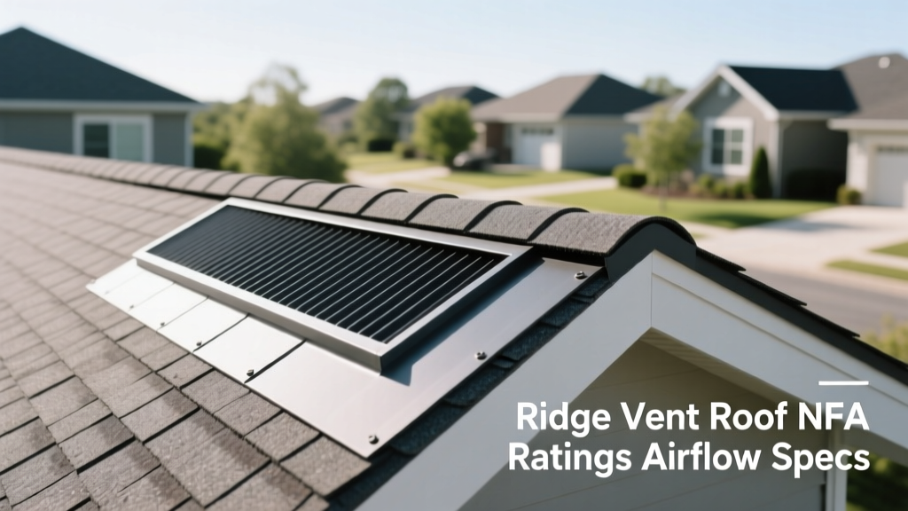
The Science of Ridge Vent Roof Airflow Metrics
A high-performing ridge vent roof relies on two primary physical forces to move air through the attic space: thermal buoyancy (the stack effect) and wind-induced pressure differentials. Thermal buoyancy occurs because hot, moisture-laden air is less dense than cooler air, causing it to rise and exit through the highest point of the roof assembly. However, relying solely on the stack effect is insufficient for modern, tightly sealed building envelopes. Wind passing over the roof ridge creates a negative pressure zone (Bernoulli's principle), which actively draws air out of the vent, significantly increasing the Cubic Feet per Minute (CFM) exchange rate.
When evaluating ridge vent roof specifications, contractors and architects must look beyond the physical dimensions of the product. The critical metric is the aerodynamic efficiency of the internal baffle system. A poorly designed baffle will allow wind to blow back into the attic (wind washing), while an overly restrictive baffle will choke the CFM output, leading to stagnant air, premature asphalt shingle degradation, and ice dam formation in cold climates.
According to the International Residential Code (IRC Section R806), the minimum net free ventilating area must be 1/150 of the attic floor space. This ratio can be reduced to 1/300 if a Class I or II vapor retarder is installed on the warm-in-winter side of the ceiling, AND at least 40% to 50% of the ventilation is provided by upper exhaust vents (like a ridge vent), with the remainder by lower intake vents.
Decoding Net Free Area (NFA) Specifications
Net Free Area (NFA) is the actual, unobstructed open space through which air can pass, measured in square inches per linear foot. A ridge vent that is 10 inches wide physically might only yield 9 to 18 square inches of NFA per linear foot, depending on the density of the internal filter mesh and the structural webbing.
When specifying materials for a ridge vent roof, it is imperative to match the exhaust NFA with the soffit intake NFA. If the ridge vent provides 18 sq. in. of NFA per foot, but the continuous soffit vent only provides 9 sq. in. per foot, the system becomes intake-starved. The ridge vent will then pull air from unintended sources, such as plumbing stacks, recessed lighting gaps, or gable vents, compromising the building's thermal envelope.
Comparative NFA Ratings: Shingle-Over vs. Aluminum
| Product Category | Model Example | NFA (sq in/lin ft) | Wind Rating | Profile Height |
|---|---|---|---|---|
| Shingle-Over (Polypropylene) | GAF Cobra III | 18.0 | 110 mph | 7/16 inch |
| Shingle-Over (Co-Polymer) | Cor-A-Vent Ridge Vent | 20.0 | 110 mph | 1/2 inch |
| Exposed Aluminum (External Baffle) | Lomanco XR-10 | 13.5 | 110 mph | 2.5 inches |
| Rolled Aluminum (Low Profile) | Active Ventilation RA-4 | 12.0 | 90 mph | 4.0 inches |
As highlighted by the Asphalt Roofing Manufacturers Association (ARMA), shingle-over polypropylene vents generally provide higher NFA per linear foot because they utilize the entire width of the roof deck slot (typically a 2-inch to 3-inch continuous cut), whereas external aluminum baffles must restrict their internal louvers to prevent rain intrusion, inherently lowering their NFA.
Weather Resistance: ASTM Standards & Baffle Engineering
A ridge vent roof must exhaust air without admitting water, snow, or insects. The industry benchmark for weather resistance is ASTM D7799 (Standard Test Method for Evaluating Resistance to Wind-Driven Rain for Roof Ventilation Products). To pass this standard, a vent must withstand simulated rain driven at wind speeds up to 110 mph without allowing moisture to penetrate the internal mesh.
Snow Infiltration & Filter Mesh Apertures
In northern climates, powder snow infiltration is a primary failure mode for ridge vents. High-performance models utilize a polypropylene or polyethylene filter mesh with an aperture size of approximately 1/8 inch (3.17 mm). This specific dimension is engineered to block snow crystals and insects (like wasps) while maintaining minimal resistance to airflow. If the mesh aperture is too large, snow will enter and melt, causing attic rot. If the mesh is too fine, it will rapidly clog with dust, pollen, and asphalt shingle granules, dropping the NFA to near zero within three to five years.
Expert Insight: Never install a ridge vent roof over a continuous ridge beam without first cutting a minimum 1.5-inch air channel on both sides of the ridge board. A common specification error is cutting only one side, which creates a turbulent bottleneck that reduces the effective CFM output by up to 40%.
Sizing Framework: Calculating Exact Ridge Vent Length
To ensure optimal performance, the exhaust specifications must be mathematically balanced with the intake. Use the following step-by-step framework to calculate the exact linear footage of ridge vent required for a specific structure.
- Calculate Attic Floor Area: Measure the length and width of the attic space. (e.g., 40 ft x 30 ft = 1,200 sq. ft.)
- Determine Total NFA Required: Divide the attic area by 300 (assuming a balanced system with a vapor retarder). (e.g., 1,200 / 300 = 4.0 sq. ft. of total NFA).
- Convert to Square Inches: Multiply by 144. (e.g., 4.0 x 144 = 576 sq. inches of total NFA).
- Split Exhaust and Intake: Divide the total NFA by 2 to ensure a 50/50 balance. (e.g., 576 / 2 = 288 sq. inches required for the ridge exhaust, and 288 sq. inches for the soffit intake).
- Calculate Linear Footage: Divide the required exhaust NFA by the NFA rating of your chosen ridge vent. If using a shingle-over vent rated at 18 sq. in. per linear foot: (e.g., 288 / 18 = 16 linear feet of ridge vent).
Common Specification Failures & Edge Cases
Even when the correct NFA materials are selected, improper integration into the roofing system can negate the performance ratings. The Building Science Corporation notes that ventilation is only effective if the air pathway is completely unobstructed from soffit to ridge.
1. Short-Circuiting the Airflow
Mixing a ridge vent with other upper exhaust types (such as gable vents, roof turbines, or powered attic fans) creates a phenomenon known as short-circuiting. The ridge vent, being the highest point, will pull air from the lower gable vents rather than drawing it from the soffits. This leaves the lower half of the attic completely stagnant and prone to severe moisture accumulation and mold growth.
2. Insulation Baffle Omission
If the soffit intake is blocked by blown-in cellulose or fiberglass batts, the ridge vent will create a severe negative pressure in the attic. This vacuum will pull conditioned, moisture-rich air from the living space below through ceiling penetrations (can lights, HVAC ducts, attic hatches). This is not a failure of the ridge vent itself, but a failure of the intake specification. Always specify rigid polystyrene or foam rafter baffles extending at least 12 inches past the interior wall plate to maintain the intake channel.
3. Shingle-Over Vent Nail Pops
When installing shingle-over ridge vents, roofing nails must be driven precisely through the designated nailing flange and into the roof deck. Over-driven nails will crush the polypropylene core, collapsing the airway and reducing the NFA to zero at that specific point. Under-driven nails will prevent the cap shingles from laying flat, creating a visual defect and a potential water entry point. Specify the use of 1.75-inch to 2-inch galvanized roofing nails, and mandate a secondary sealant bead of roofing cement over the final cap shingle fasteners as per manufacturer wind-warranty requirements.