Roof Flashing Specifications: ASTM Standards and Gauge Requirements
Technical specifications for roof flashing materials, including ASTM standards, minimum gauge requirements, and thermal expansion data.
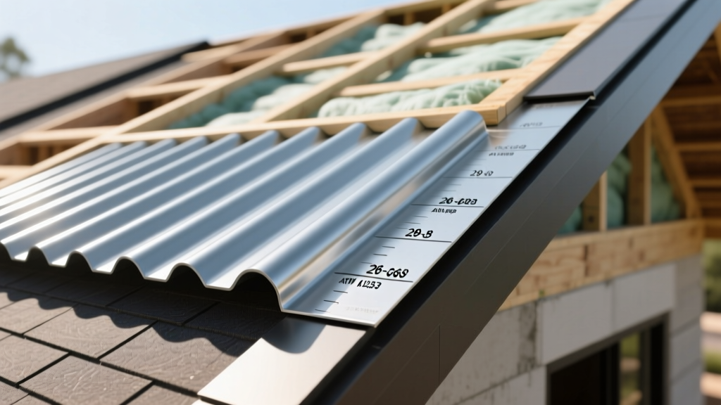
Roof field failures rarely occur in the center of a shingle or membrane; they occur at the intersections. Chimneys, dormers, valleys, and parapets are the primary ingress points for water, making the technical specifications of your roof flashing the most critical variable in the entire roofing assembly. Selecting flashing based on visual appeal or initial cost rather than metallurgical performance and dimensional stability guarantees premature system failure. This guide details the exact ASTM standards, minimum gauge requirements, and thermal expansion coefficients required to specify high-performance roof flashing for residential and commercial applications.
Governing ASTM Standards for Flashing Materials
Every metal flashing material deployed on a roof must comply with specific American Society for Testing and Materials (ASTM) standards. These standards dictate the chemical composition, yield strength, and coating weights that determine how the material will perform under UV exposure, thermal cycling, and mechanical stress.
Copper (ASTM B370)
Copper flashing must conform to ASTM B370, which specifies cold-rolled copper sheet for architectural applications. The standard mandates a minimum tensile strength of 30,000 psi for the H00 (quarter-hard) temper, which is the minimum acceptable temper for roofing to prevent sagging and oil-canning. Cold-rolled copper (H04) is preferred for flat-lock seams but is too brittle for complex formed step flashing.
Galvanized Steel (ASTM A653)
Galvanized steel flashing falls under ASTM A653. The critical specification here is the zinc coating weight. For exterior roof flashing, you must specify a G90 coating designation, which guarantees a minimum of 0.90 ounces of zinc per square foot (total both sides). G60 coatings, frequently found in big-box store pre-bent flashing, will exhibit red rust within 3 to 5 years in coastal or high-humidity environments.
Aluminum (ASTM B209)
Aluminum sheet and plate for flashing are governed by ASTM B209. The industry standard alloy for architectural flashing is 3003-H14. The addition of manganese in the 3003 series provides roughly 20% higher tensile strength than pure 1100 aluminum, while the H14 strain-hardened temper ensures the material holds its formed shape under wind uplift loads without becoming brittle.
Material Gauge and Thickness Specification Matrix
Gauge numbers are notoriously inconsistent across different metals; a 24-gauge steel sheet is significantly thicker than a 24-gauge aluminum sheet. Therefore, professional specifications must always mandate decimal inch or millimeter thicknesses alongside the nominal gauge. The following matrix outlines the absolute minimum thicknesses for standard roof flashing applications, referencing the SMACNA Architectural Sheet Metal Manual.
| Material | Nominal Gauge | Minimum Thickness (Inches) | Minimum Thickness (mm) | Expected Service Life |
|---|---|---|---|---|
| Cold-Rolled Copper | 16 oz / 20 oz | 0.0216" / 0.0270" | 0.55 mm / 0.68 mm | 60+ Years |
| Galvanized Steel (G90) | 24 Gauge | 0.0239" | 0.60 mm | 25 - 40 Years |
| Aluminum (3003-H14) | 0.019" Sheet | 0.0190" | 0.48 mm | 30 - 50 Years |
| Stainless Steel (304) | 28 Gauge | 0.0149" | 0.38 mm | 50+ Years |
Thermal Expansion Coefficients and Joint Spacing
One of the most frequent causes of flashing failure is tearing at the fastener line due to unaccounted thermal expansion and contraction. Metals expand and contract at vastly different rates when subjected to the extreme temperature deltas found on a roof surface, where ambient air might be 20°F but the dark roof surface can reach 140°F in direct sunlight.
Calculating Thermal Movement
The formula for linear thermal expansion is: ΔL = α × L × ΔT
- ΔL: Change in length
- α: Coefficient of thermal expansion
- L: Initial length of the flashing run
- ΔT: Temperature change (°F)
Consider a 20-foot (240-inch) continuous run of aluminum parapet coping or base flashing experiencing a 100°F temperature swing. Aluminum has a coefficient (α) of 13.1 × 10⁻⁶ in/in/°F. The expansion calculation is: 13.1 × 10⁻⁶ × 240 × 100 = 0.314 inches. If this 20-foot run is rigidly pinned with screws every 12 inches without slip joints, the accumulated stress will either shear the fasteners, elongate the screw holes, or tear the metal at the hem.
Maximum Recommended Run Lengths
To mitigate thermal stress without requiring complex expansion joints, adhere to these maximum continuous run lengths before introducing a slip-joint or expansion cleat:
- Copper: 32 feet maximum continuous run.
- Galvanized / Stainless Steel: 40 feet maximum continuous run (due to lower expansion coefficients of roughly 6.5 to 9.3 × 10⁻⁶).
- Aluminum: 24 feet maximum continuous run.
Galvanic Corrosion and Dissimilar Metal Isolation
When two dissimilar metals are in direct contact in the presence of an electrolyte (rainwater, condensation, or snowmelt), galvanic corrosion occurs. The less noble metal (the anode) will corrode rapidly to protect the more noble metal (the cathode). This is a primary failure mode when installers mix flashing materials or use incorrect fasteners.
Isolation Protocols
If architectural requirements demand the intersection of dissimilar metals (e.g., a copper roof valley transitioning to a galvanized steel gutter), you must break the electrical path. Specify the use of 30-mil butyl rubber flashing tape, heavy-duty EPDM separators, or a continuous bead of ASTM C920 Class 25 polyurethane sealant between the mating surfaces. Fasteners must be isolated using neoprene or EPDM washers.
Fastener and Sealant Compatibility Matrix
The performance of roof flashing is entirely dependent on the hardware used to secure it. The NRCA Roofing Manual explicitly warns against using standard electroplated hardware store screws for exterior flashing, as the zinc plating is typically less than 0.0002 inches thick and will fail rapidly.
| Flashing Material | Approved Fastener Type | Compatible Sealant (ASTM C920) | Prohibited Hardware |
|---|---|---|---|
| Copper | Copper, Stainless Steel (304/316), or Silicon Bronze | Polyurethane, Lead-free solder | Galvanized steel, Aluminum |
| Galvanized Steel | Hot-Dipped Galvanized (HDG) or Stainless Steel | Polyurethane, Silicone | Bare steel, Copper |
| Aluminum | Aluminum or Stainless Steel (with isolation washer) | Silicone, Polyurethane (non-acidic) | Copper, Uncoated Steel |
| Stainless Steel | Stainless Steel (matching grade) | Silicone, Polyurethane | Carbon steel, Galvanized |
When specifying sealants for flashing termination bars and reglets, avoid cheap acrylic or butyl caulks. Require ASTM C920 Class 25 or Class 50 sealants, which are tested to withstand ±25% or ±50% joint movement without losing adhesion or cohesive strength. Polyurethane sealants offer superior tear strength and paintability, while neutral-cure silicones provide the highest UV resistance and longevity, though they cannot be painted.
Verifying Mill Test Reports (MTRs)
For commercial projects or high-end residential builds, do not rely solely on the supplier's invoice description to verify material specs. Require the roofing contractor to submit Mill Test Reports (MTRs) for all coil stock used to fabricate the flashing. The MTR will confirm the exact alloy, the temper (e.g., H14 vs H24), the measured decimal thickness, and the coating weight. Reviewing the MTR ensures that the 24-gauge G90 galvanized steel you specified and paid for was not substituted with a lighter 26-gauge G60 coil at the fabrication shop, a common practice that compromises the entire roofing warranty.