Cable Insulation Material Installation Techniques for Cable Trays
Master cable insulation material installation in commercial trays. Learn fire-stopping, thermal management, and jacket-specific termination techniques.

The Critical Role of Installation Technique in Dielectric Integrity
Electrical infrastructure in commercial and industrial facilities relies entirely on the physical and chemical integrity of the cable insulation material. While design engineers specify the correct dielectric properties and voltage ratings, it is the field installer's technique that determines whether the system will survive decades of thermal cycling, mechanical stress, and fault conditions. Mishandling the cable insulation material during pulling, bending, or termination introduces micro-fissures, compromises the semi-conductive shields, and leads to partial discharge or catastrophic dielectric breakdown.
This guide details advanced installation techniques for handling, routing, and terminating modern cable insulation materials—specifically Cross-linked Polyethylene (XLPE), Ethylene Propylene Rubber (EPR), and Polyvinyl Chloride (PVC)—within commercial cable tray systems and fire-rated penetrations.
Material-Specific Handling and Environmental Constraints
Different cable insulation materials exhibit distinct mechanical behaviors under physical stress and temperature variations. Ignoring these material-specific constraints is the leading cause of jacket failure prior to system energization.
PVC (Polyvinyl Chloride) and Cold-Weather Brittleness
PVC remains a standard for low-voltage (600V) building wire due to its cost-effectiveness and flame retardancy. However, PVC undergoes a glass transition at lower temperatures, making the cable insulation material highly susceptible to micro-cracking when bent in cold environments. If ambient temperatures drop below 40°F (4°C), installers must deploy thermal blankets or heated enclosures around the cable reels for a minimum of 24 hours prior to pulling. Bending a cold PVC jacket will cause invisible longitudinal splits that eventually allow moisture ingress and track faults.
XLPE (Cross-linked Polyethylene) and Moisture Sensitivity
XLPE is the dominant cable insulation material for medium-voltage (5kV–35kV) commercial feeders. It offers superior thermal endurance (rated for 90°C continuous, 130°C emergency overload). Unlike thermoplastic PVC, XLPE is a thermoset material; it will not melt under high heat, but it is highly vulnerable to water treeing if the outer jacket is compromised. During installation, any scoring of the outer jacket must be immediately repaired using manufacturer-approved heat-shrink tubing or liquid epoxy sealants to prevent moisture from reaching the XLPE layers.
Never use petroleum-based or generic silicone lubricants when pulling XLPE or EPR insulated cables. Hydrocarbon-based pulling compounds can cause environmental stress cracking (ESC) in polymeric jackets. Always use manufacturer-approved, high-dielectric pulling lubricants specifically formulated for the cable insulation material, such as Polywater J or equivalent polyethylene-oxide based compounds.
Cable Tray Fill Ratios and Thermal Dissipation
The thickness and thermal conductivity of the cable insulation material directly impact heat dissipation in cable trays. Overfilling a tray traps heat, forcing the insulation to operate above its rated temperature, which halves the material's lifespan for every 10°C increase in operating temperature (per the Arrhenius equation).
Compliance with NFPA 70 (National Electrical Code) Article 392 is mandatory for cable tray fill capacities. The table below outlines how different insulation types affect tray fill and thermal management strategies.
| Insulation Material | Max Continuous Temp | Relative Thickness (15kV) | Tray Fill Limit (NEC 392) | Thermal Management Strategy |
|---|---|---|---|---|
| PVC | 75°C | Thick (requires robust mechanical protection) | 50% of cross-sectional area | Maintain 1 cable diameter spacing for multi-conductor |
| XLPE | 90°C | Thin (high dielectric strength allows compact design) | 50% (Control) / 40% (Power) | Use aluminum trays for superior heat sinking |
| EPR | 90°C | Medium (flexible but requires thicker layers than XLPE) | 40% of cross-sectional area | Avoid bundling; utilize ladder-style trays for airflow |
| Mineral Insulated (MI) | 250°C+ | Ultra-thin (Magnesium oxide powder core) | No specific fill limit (derating applies) | Can be stacked, but requires derating calculations |
Fire-Stopping Penetrations for Insulated Cable Bundles
When cable trays penetrate fire-rated walls or floors, the cable insulation material itself can act as a fuel path, allowing fire and toxic smoke to bypass the building's passive fire protection. Standard polymeric insulations will combust or melt, leaving voids in the firewall. Installers must use tested and listed firestop systems, such as those documented in the UL Firestop Directory, to seal these penetrations.
Step-by-Step Intumescent Sealant Installation
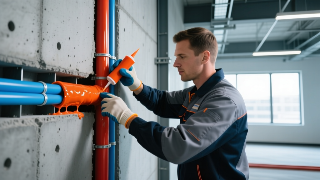
For penetrations containing XLPE or PVC insulated cables, intumescent firestop sealants (e.g., Hilti CP 606 or 3M Fire Barrier Sealant FD 150) are required. These materials expand when exposed to heat, crushing the melting cable insulation material and sealing the void.
- Preparation: Clean the cable jackets and the concrete/masonry opening. Remove all dust, oil, and moisture. The cable insulation material must be free of pulling lubricants in the sealant zone, as lubricants can prevent the firestop material from adhering.
- Backing Material Installation: Pack the void with mineral wool batts. The mineral wool must be compressed by at least 50% to ensure a tight fit. Leave a recess of 3/4 inch (19mm) to 1 inch (25mm) from the face of the wall for the intumescent sealant.
- Cable Spacing: Ensure individual cables are separated by at least 1/2 inch (12mm) within the penetration. If the cable insulation material touches adjacent cables, the intumescent sealant cannot flow between them, compromising the F-rating (flame rating) and T-rating (temperature rating) of the assembly.
- Sealant Application: Apply the intumescent sealant using a pneumatic caulking gun. Tool the sealant with a putty knife to ensure it fully encapsulates the circumference of each cable jacket and bonds to the mineral wool and substrate.
- Collars and Wraps: For plastic conduit containing cables, install an intumescent firestop collar on the outside of the penetration. As the conduit melts, the collar expands inward, pinching the conduit and the internal cable insulation material shut.
Medium Voltage Termination and Insulation Shield Management
Terminating medium-voltage cables requires extreme precision. The cable insulation material (typically XLPE) is covered by a semi-conductive shield that smooths the electrical field. During termination, this shield must be stripped back to a specific dimension without scoring the primary insulation beneath it.
When stripping the semi-conductive layer from 15kV XLPE cable, never use a standard utility knife with a plunging cut. Use a specialized scoring tool (such as the Ripley SD-1 or a calibrated S.C. blade) set to a depth that only cuts the semi-conductive layer. Score longitudinally and peel the shield off in strips. Finally, use a glass scraper or specialized chamfering tool to "pencil-point" or bevel the edge of the remaining semi-conductive shield. This prevents sharp electrical stress cones from forming at the transition point between the shield and the bare cable insulation material.
Stress Control and Cold Shrink Application
Once the cable insulation material is exposed and cleaned with an approved solvent (never use general-purpose degreasers, which can leave conductive residues), a stress control tube must be applied. Modern terminations utilize cold-shrink technology—pre-stretched EPDM or silicone rubber tubes on a removable plastic core.
Position the stress control tube exactly over the semi-conductive break. Pull the core cord evenly. As the tube shrinks, it exerts constant radial pressure on the cable insulation material, eliminating air voids where partial discharge could initiate. Ensure the mastic seal at the base of the termination fully encapsulates the outer jacket to prevent longitudinal moisture migration under the termination boot.
Summary of Best Practices
The longevity of commercial electrical systems is dictated by how well the installer respects the physical limits of the cable insulation material. By adhering to strict environmental controls during cold-weather pulls, calculating accurate tray fill ratios to manage thermal dissipation, executing code-compliant fire-stopping penetrations, and utilizing precision tools for medium-voltage terminations, contractors can eliminate the most common vectors for premature dielectric failure. Always consult the specific manufacturer's installation manual and adhere to the latest OSHA electrical safety standards and local code amendments before commencing work.
Written by
James ThorntonJames Thornton is a construction industry veteran with 25 years of hands-on experience in wood framing, lumber grading, and residential building codes. He started as a framing carpenter in rural Oregon, earned his ICC Residential Building Inspector certification, and eventually became a senior plan reviewer for the City of Portland Bureau of Development Services. James holds a B.S. in Wood Science & Technology from Oregon State University and is a certified lumber grader through the West Coast Lumber Inspection Bureau (WCLIB). He has inspected over 3,000 residential construction sites and authored the city's internal guide on advanced framing techniques (2x6 at 24" O.C.). James lives in Bend, OR, where he builds custom timber-frame cabins and competes in lumberjack sports.
More from James Thornton
View all
Insulation
Best Home Insulation Materials: Complete 2026 Guide
Compare top home insulation materials for 2026. Find R-values, installed costs per square foot, and best uses for fiberglass, spray foam, and mineral wool.
Aug 4, 2026

Sustainable Building
Certify Your Green Building Material for LEED and WELL
Step-by-step guide to certifying a green building material for LEED v5 and WELL v2. Master EPDs, HPDs, and VOC limits for 2026 project specifications.
Aug 4, 2026

Stone & Masonry
Veneer Stacked Stone Panels: Interior Design & Style Showcase
Discover how veneer stacked stone panels transform interiors. Explore modern design profiles, material pairings, and technical installation specs.
Aug 4, 2026