Step-by-Step Wall Soundproofing: Installing Resilient Channels & MLV
Learn the exact installation procedures for wall soundproofing using resilient channels and mass loaded vinyl to achieve STC 50+ acoustic ratings.
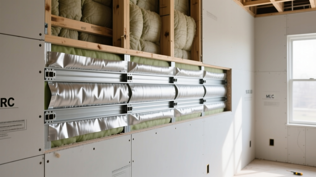
The Physics of Decoupling and Mass in Wall Assemblies
Achieving a Sound Transmission Class (STC) rating of 50 or higher in standard wood-framed construction requires addressing three acoustic principles: mass, decoupling, and damping. Standard fiberglass batts alone only absorb internal cavity resonance; they do not block airborne noise. By combining Mass Loaded Vinyl (MLV) with RC-1 resilient channels, you create a constrained-layer mass system that is mechanically isolated from the structural framing. This guide details the precise installation procedures required to prevent acoustic short-circuiting and flanking paths, ensuring your wall assembly performs to its laboratory-tested potential.
Material Specifications and Cost Matrix
Procuring the correct material grades is critical. Substituting standard drywall for high-density acoustic boards or using the wrong screw length will compromise the entire assembly. Below is the 2026 material breakdown for a standard 100-square-foot wall section.
| Material | Specification / Model | Est. Cost (per sq ft) | Acoustic Function |
|---|---|---|---|
| Base Drywall | 5/8-inch Type X Gypsum | $0.65 - $0.80 | Low-frequency mass |
| Mass Loaded Vinyl | 1 lb/sq ft MLV (e.g., TMS or Soundsulate) | $1.50 - $1.85 | High-frequency blocking & limp mass |
| Resilient Channels | RC-1 (25-gauge steel, 7/8-inch depth) | $0.35 - $0.45 | Mechanical decoupling |
| Face Drywall | 5/8-inch Type X Gypsum | $0.65 - $0.80 | Exterior mass layer |
| Acoustic Sealant | OSI SC-175 or Tremco Acousti-Seal | $0.25 (per linear ft) | Airtight perimeter sealing |
Phase 1: Cavity Preparation and Flanking Prevention
Before installing any mass or channels, the stud cavity must be prepped to eliminate flanking paths—routes where sound bypasses the insulation entirely.
- Install Mineral Wool: Friction-fit Rockwool Safe'n'Sound (2.5 lb/cu ft density) into the stud bays. Do not compress it; compression reduces its sound-absorbing coefficients.
- Seal Electrical Boxes: Standard plastic electrical boxes are massive acoustic leaks. Wrap every box in a TradeMate Acoustical Putty Pad (minimum 1/8-inch thickness). Ensure the putty extends at least 1 inch beyond the edges of the box onto the drywall backing.
- Backer Rods for Gaps: Any gap larger than 1/4 inch between the bottom plate and the subfloor must be stuffed with closed-cell backer rod before applying acoustic sealant.
Phase 2: Base Drywall and Mass Loaded Vinyl (MLV)
The first layer of mass is applied directly to the studs, creating a rigid backing for the decoupled face layer.
- Hang the Base Layer: Install 5/8-inch Type X drywall horizontally. Fasten with 1-1/4-inch coarse-thread drywall screws every 12 inches along the studs. Stagger vertical joints.
- Deploy the MLV: Roll out the 1 lb/sq ft Mass Loaded Vinyl horizontally over the base drywall. MLV is heavy (100 lbs per 4x25 roll); use two installers or a drywall lift.
- Overlap and Seal: Overlap all MLV seams by exactly 2 inches. Seal the overlaps with 2-inch wide acoustic seam tape. Do not use standard drywall tape or duct tape, as the plasticizers in the vinyl will degrade standard adhesives over time.
- Perimeter Fastening: Staple the top and bottom edges of the MLV to the framing using a heavy-duty pneumatic stapler. The MLV should not be tightly stretched; it must remain 'limp' to effectively dissipate acoustic energy.
Phase 3: Mounting RC-1 Resilient Channels
This is the most critical phase. According to the USG Acoustic Design Guidelines, improper fastening of resilient channels is the leading cause of field-failed STC ratings.
- Spacing: Install RC-1 channels horizontally, spaced exactly 24 inches on center (OC). Start the first channel 2 inches from the ceiling, and maintain 24-inch spacing down the wall. The final channel should be within 6 inches of the floor.
- Fasteners: Use 1-5/8-inch Type S fine-thread drywall screws to attach the channels only to the wood studs. Drive the screw through the channel flange, through the MLV, through the base drywall, and into the stud.
- The 1/2-Inch Rule: Stop the channels 1/2 inch short of the ceiling, floor, and adjoining walls. If the channel touches the adjacent structure, vibration will transfer directly into the flanking surfaces, bypassing the decoupling.
If a screw used to attach the face drywall (Phase 4) is driven too deep and penetrates the base drywall into the wood stud, it creates a rigid mechanical bridge. A single short-circuited screw can drop the wall's STC rating by 8 to 12 points. Use a depth-sensitive screw gun (dimpler) set to stop exactly flush with the face paper of the final drywall layer.
Phase 4: Face Drywall and Perimeter Acoustic Sealing
The final layer completes the decoupled mass-spring-mass system.
- Hang the Face Layer: Install the second layer of 5/8-inch Type X drywall horizontally over the resilient channels. Fasten with 1-1/4-inch fine-thread screws into the center of the channel flange.
- Stagger Joints: Ensure no vertical or horizontal joints align with the base drywall layer. Misalign joints by at least 12 inches.
- Apply Acoustic Sealant: Before taping and mudding, run a continuous 3/8-inch bead of non-hardening acoustic sealant (like OSI SC-175) along the entire perimeter where the face drywall meets the floor, ceiling, and adjacent walls. This sealant remains pliable indefinitely, absorbing structural vibration and blocking airborne leaks.
Testing, Troubleshooting, and STC Verification
Once the wall is finished and painted, perform a rudimentary field test. While formal laboratory testing requires adherence to the ASTM E90 Standard for Airborne Sound Transmission, you can identify gross installation failures using a high-decibel Bluetooth speaker placed in the adjacent room.
Common Failure Modes and Fixes
| Symptom | Probable Cause | Remediation Strategy |
|---|---|---|
| High-pitched noise (voices, TV treble) bleeds through specific spots. | Unsealed electrical boxes or missing MLV overlap tape. | Cut access holes, apply acoustic putty pads to boxes, and inject expanding acoustic foam into gaps. |
| Low-frequency bass (subwoofers, HVAC rumble) vibrates the wall. | Resilient channels touching the floor/ceiling, or drywall short-circuiting into studs. | Score and remove drywall at perimeters to establish the 1/2-inch gap; re-apply acoustic sealant. |
| Sound travels through the wall but is heard 10 feet away in the next room. | Flanking via shared HVAC ductwork or continuous hardwood flooring. | Install flexible canvas duct connectors and use acoustic underlayment breaks at thresholds. |
Proper execution of this MLV and resilient channel assembly transforms a standard partition into a professional-grade acoustic barrier. The key to success lies not in the materials themselves, but in the meticulous sealing of perimeters and the absolute prevention of rigid mechanical bridges between the decoupled face and the structural framing.