Technical Specs for Stone Veneer Columns: Framing & Load Limits
Master stone veneer column technical specs, including structural framing, ASTM weight limits, moisture management, and fastening requirements.

Core Structural Framing and Deflection Limits
Designing stone veneer columns requires strict adherence to structural framing and deflection criteria. Unlike flat wall applications, columns are freestanding or semi-freestanding structures that experience multi-directional wind loads and potential impact forces. The underlying framing must support the dead load of the veneer while restricting lateral deflection to prevent mortar joint cracking and veneer delamination.
For wood-framed columns, utilize minimum 2x4 or 2x6 dimensional lumber studs spaced at a maximum of 16 inches on center (O.C.). For commercial or high-load applications, 20-gauge or 16-gauge cold-formed steel studs are required. The critical engineering metric for any masonry veneer substrate is the deflection limit. According to the Brick Industry Association Technical Notes, the maximum allowable deflection for anchored masonry veneer framing is L/600. For a standard 10-foot (120-inch) column, the framing must not deflect more than 0.2 inches under maximum design loads.
Stone veneer is strictly a non-load-bearing cladding. The column framing must support the roof, beam, or overhang load independently. The veneer and its mortar scratch coat add significant dead weight but contribute zero structural capacity to the column assembly. Never rely on the masonry veneer to stabilize an under-framed column.
ASTM Weight Load Matrix and Material Specifications
Material selection directly dictates the framing gauge and fastener schedule. Natural stone and manufactured stone veneer (MSV) have drastically different weight profiles. All manufactured products must comply with ASTM C1670, which governs the physical properties, freeze-thaw durability, and density limits of MSV.
| Material Type | Average Weight (psf) | Max Column Load (10ft x 2ft) | Required Stud Gauge/Size |
|---|---|---|---|
| Manufactured Stone Veneer | 10 - 15 lbs | 200 - 300 lbs | 2x4 Wood / 20ga Steel |
| Natural Limestone / Sandstone | 25 - 35 lbs | 500 - 700 lbs | 2x6 Wood / 16ga Steel |
| Natural Granite / Slate (Full Bed) | 35 - 50+ lbs | 700 - 1000+ lbs | 2x6 Wood / 14ga Steel |
When calculating total column load, always add a 20% safety factor to account for the weight of the metal lath, mortar scratch coat, and setting mortar. A 2x2 foot manufactured stone column that is 10 feet tall will easily exceed 350 lbs when fully assembled.
360-Degree Moisture Management for Columns
Columns are uniquely vulnerable to moisture intrusion because they are exposed to wind-driven rain from all four sides. Capillary action and hydrostatic pressure can force water behind the veneer if the weather-resistive barrier (WRB) and drainage plane are not continuous. The National Veneer Masonry Association (NVMA) mandates a continuous drainage cavity for all exterior veneer applications.
Drainage Plane Assembly Sequence
- Sheathing Preparation: Install exterior-rated OSB or plywood sheathing. Tape all seams with compatible flashing tape to create a secondary air barrier.
- Primary WRB: Apply a code-approved housewrap (e.g., Tyvek CommercialWrap) over the sheathing. Wrap the housewrap completely around the column, overlapping the trailing edge by a minimum of 6 inches.
- Secondary WRB (Grade D Paper): Install a layer of ASTM D226 Grade D building paper over the housewrap. This acts as a bond-breaker and secondary moisture barrier, absorbing incidental moisture that penetrates the mortar.
- Flashing Integration: Install base flashing at the foundation intersection, extending up the column a minimum of 8 inches. Integrate kick-out flashing at the top of the column where it meets the soffit or roofline to divert water away from the assembly.
- Weep Screed Installation: Fasten a galvanized weep screed (ASTM C847) at the base of the column. The screed must feature weep holes spaced no more than 33 inches O.C. to allow trapped moisture to escape the drainage cavity.
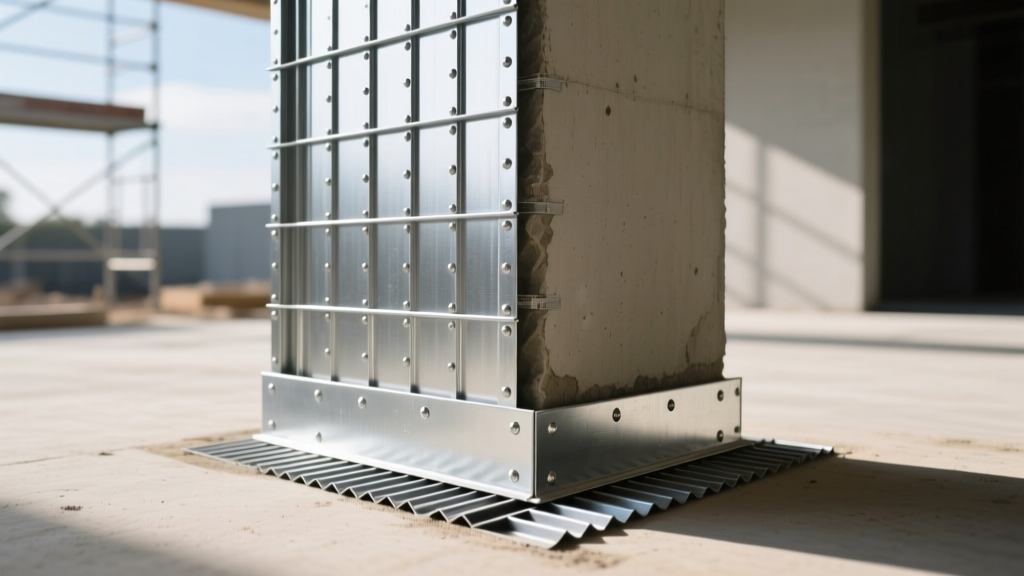
Metal Lath, Fasteners, and Scratch Coat Tolerances
The mechanical bond between the mortar and the column framing relies entirely on the metal lath specification and fastening schedule. Use only 2.5 lb per square yard self-furring galvanized steel lath (ASTM C847). The self-furring dimples ensure the lath sits 1/4 inch away from the WRB, allowing the scratch coat mortar to fully encapsulate the wire mesh.
- Lath Overlap: Overlap horizontal seams by 2 inches and vertical seams by 1 inch. At column corners, the lath must wrap continuously around the corner by at least 4 inches; never terminate the lath exactly at the corner edge, as this creates a structural hinge point prone to cracking.
- Fastener Specs: Use hot-dipped galvanized roofing nails or self-drilling steel framing screws with neoprene washers. Fasteners must penetrate the underlying wood studs by a minimum of 1 inch, or pass through steel studs by at least 3/8 inch.
- Fastener Schedule: Space fasteners every 6 inches O.C. along the studs and every 12 inches O.C. between studs. On a standard 2x2 column, this requires approximately 40 to 50 fasteners per vertical layer of lath.
Following lath installation, apply a 1/2-inch to 3/4-inch scratch coat of Type S mortar. Type S mortar is mandatory for exterior columns due to its high tensile strength (minimum 1,800 psi) and superior bond characteristics compared to Type N mortar (750 psi). Score the scratch coat horizontally with a raking tool to provide a mechanical key for the final setting mortar. Cure the scratch coat for 24 to 48 hours, keeping it damp to prevent rapid moisture loss and shrinkage cracking.
Column-Specific Failure Modes and Mitigation
Column applications present unique failure vectors not found in continuous wall planes. Understanding these edge cases is critical for long-term durability.
1. Corner Delamination: The most common failure on stone columns occurs at the 90-degree corners. If manufactured corner pieces are used, they must be bedded in a full mortar joint. If natural stone is used, masons must employ a 'woven corner' technique, alternating the overlapping stone by at least 4 inches per course. A continuous vertical mortar joint at the corner will inevitably crack due to differential thermal expansion.
2. Efflorescence Staining: Because columns are often surrounded by concrete patios or landscaping, ground moisture can wick up the column base via capillary action. Mitigate this by installing a capillary break (such as a 1/4-inch closed-cell foam backer rod or a specialized flashing membrane) between the concrete slab and the bottom plate of the column framing before installing the weep screed.
'When wrapping a column with stacked stone, avoid using panelized veneer systems that rely on hidden clips unless the manufacturer explicitly rates the clips for multi-plane, 360-degree column applications. Standard panel clips are engineered for flat-shear loads and can fail when subjected to the compound angles and torsional forces present in freestanding columns.'
3. Mortar Joint Shrinkage: Applying mortar joints thicker than 1/2 inch on column applications leads to excessive shrinkage as the mortar cures, pulling the stone away from the scratch coat. Maintain strict 1/2-inch joint tolerances and use a polymer-modified mortar mix for exterior columns to increase flexibility and reduce shrinkage cracking during seasonal temperature fluctuations.
Written by
James ThorntonJames Thornton is a construction industry veteran with 25 years of hands-on experience in wood framing, lumber grading, and residential building codes. He started as a framing carpenter in rural Oregon, earned his ICC Residential Building Inspector certification, and eventually became a senior plan reviewer for the City of Portland Bureau of Development Services. James holds a B.S. in Wood Science & Technology from Oregon State University and is a certified lumber grader through the West Coast Lumber Inspection Bureau (WCLIB). He has inspected over 3,000 residential construction sites and authored the city's internal guide on advanced framing techniques (2x6 at 24" O.C.). James lives in Bend, OR, where he builds custom timber-frame cabins and competes in lumberjack sports.
More from James Thornton
View all
Insulation
Best Home Insulation Materials: Complete 2026 Guide
Compare top home insulation materials for 2026. Find R-values, installed costs per square foot, and best uses for fiberglass, spray foam, and mineral wool.
Aug 4, 2026

Sustainable Building
Certify Your Green Building Material for LEED and WELL
Step-by-step guide to certifying a green building material for LEED v5 and WELL v2. Master EPDs, HPDs, and VOC limits for 2026 project specifications.
Aug 4, 2026

Stone & Masonry
Veneer Stacked Stone Panels: Interior Design & Style Showcase
Discover how veneer stacked stone panels transform interiors. Explore modern design profiles, material pairings, and technical installation specs.
Aug 4, 2026