Stone Veneer Foundation Wall Technical Specs and Moisture Details
Technical specifications for stone veneer foundation walls, covering load limits, moisture management, weep screed clearances, and ASTM mortar standards.

Core Structural and Load-Bearing Requirements
Applying stone veneer to a foundation wall requires strict adherence to weight distribution and substrate stability guidelines. Unlike standard above-grade wood framing, foundation walls—typically composed of poured concrete or Concrete Masonry Units (CMU)—offer superior load-bearing capacity. However, the transition zone between the foundation and the framed structure above introduces critical shear and differential settlement risks.
When transitioning from a concrete foundation to a wood-framed first floor, the stone veneer must not bridge the structural joint. Differential settlement between the foundation and the framed structure will induce shear forces that crack the mortar matrix. Install a continuous expansion joint at the foundation-to-framing transition, utilizing a compressible backer rod and a high-quality polyurethane sealant to accommodate vertical movement while maintaining the weather-resistant barrier (WRB).
Moisture Management and Flashing Specifications
Foundation walls are highly susceptible to hydrostatic pressure, capillary action, and splashback. Moisture management is the single most critical factor in preventing efflorescence and mortar delamination. The International Residential Code (IRC) Chapter 7 mandates specific clearances and flashing protocols for exterior wall coverings.
Weep Screed and Grade Clearances
A corrosion-resistant weep screed must be installed at the base of the stone veneer system to allow trapped moisture to escape. The technical specifications for foundation applications are non-negotiable:
- Material: Minimum 0.019-inch thick galvanized steel or rigid PVC with a minimum 3-inch vertical flange.
- Earth Clearance: The bottom edge of the weep screed must be positioned a minimum of 4 inches above the finished earth grade.
- Paved Surface Clearance: Where the foundation meets concrete patios, walkways, or driveways, the weep screed must maintain a minimum 2-inch clearance above the paved surface.
Weather-Resistant Barrier (WRB) Integration
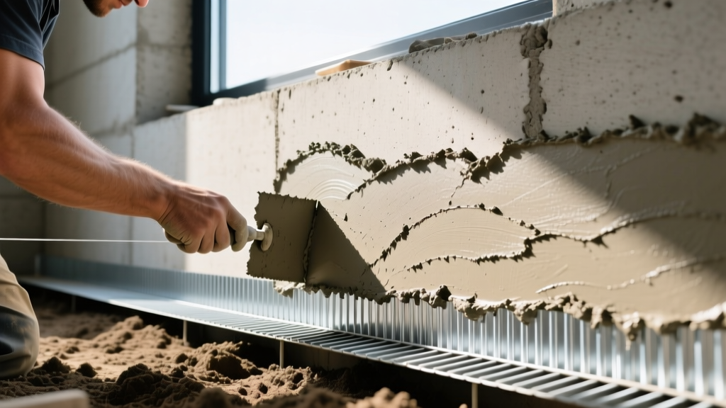
For CMU or poured concrete foundations, a parge coat (1/2-inch Portland cement plaster) is often applied to smooth the surface. However, a fluid-applied or sheet-based WRB is still required over the parge coat before attaching metal lath. The WRB must lap over the weep screed's vertical flange by a minimum of 2 inches, creating a shingle effect that directs water outward and away from the structural substrate.
Material Specifications Matrix: Adhered vs. Anchored Systems
Selecting the correct veneer system depends on the foundation's structural profile, local seismic requirements, and the specific stone product. The following matrix outlines the technical parameters for foundation applications.
| Veneer System | ASTM Standard | Max Weight Limit | Foundation Substrate Suitability | Fastening / Bond Mechanism |
|---|---|---|---|---|
| Adhered Manufactured Stone | ASTM C1670 | 15 psf | Excellent (Direct bond to CMU/Concrete via lath and mortar) | Scratch coat and setting bed mortar bond |
| Adhered Natural Stone | ASTM C1780 | 15 psf (Standard) Up to 40 psf (Engineered) |
Good (Requires structural engineer approval for >15 psf loads) | Thin-set mortar or traditional scratch/setting bed |
| Anchored Natural Stone | ASTM C1877 | Unlimited (Structural dependent) | Excellent (Requires concrete ledge or structural shelf angle) | Corrosion-resistant metal ties anchored to substrate |
Mortar, Grout, and Lath Technical Standards
The longevity of a stone veneer foundation installation relies heavily on the chemical and mechanical properties of the lath and mortar assembly. Adherence to Masonry Veneer Manufacturers Association (MVMA) guidelines and ASTM standards is mandatory.
Galvanized Steel Lath Specifications
For adhered systems on concrete or CMU foundations, self-furring, galvanized steel woven wire lath is required to provide a mechanical key for the mortar.
- Weight: Minimum 2.5 pounds per square yard (ASTM C847).
- Fastening: Concrete nails or powder-actuated fasteners with corrosion-resistant washers. Fasteners must penetrate the concrete substrate a minimum of 1 inch.
- Spacing: Maximum 6 inches on center (o.c.) at edges and 16 inches o.c. in the field.
- Overlaps: Lath must overlap a minimum of 1 inch at horizontal seams and 2 inches at vertical seams. Horizontal overlaps must be shingled (upper layer overlapping the lower layer) to prevent moisture migration behind the mesh.
Mortar Mix and Hydration
Standard Type N mortar is insufficient for exterior foundation applications due to its lower compressive strength and higher permeability. Specify Type S mortar, which delivers a minimum compressive strength of 1,800 psi. For foundations in climates with severe freeze-thaw cycles, integrate a polymer-modified acrylic fortifier into the mixing water. This reduces the water-cement ratio, decreases capillary porosity, and enhances flexural bond strength. The scratch coat must be applied at a thickness of 1/2-inch to 3/4-inch, completely encapsulating the lath, and scarified horizontally to provide a mechanical key for the 1/2-inch setting bed.
Common Failure Modes and Engineering Mitigations
Foundation stone veneer failures are rarely caused by the stone itself; they are almost exclusively the result of moisture mismanagement or substrate deflection. Understanding these failure modes allows for proactive engineering mitigations.
1. Subflorescence and Spalling
The Mechanism: Water-soluble salts from the Portland cement mortar or the CMU foundation migrate to the surface. If the stone is highly porous and the exterior environment is cold, the salts crystallize just beneath the stone's face (subflorescence), generating expansive pressures that spall the stone face.
Mitigation: Apply a penetrating, breathable silane/siloxane water repellent to the stone and mortar joints 28 days after installation. Never use film-forming acrylic sealers, which trap vapor inside the masonry assembly. For detailed chemistry on salt migration, refer to the National Concrete Masonry Association (NCMA) TEK 19-2B on Efflorescence.
2. Delamination at the Parge Coat Interface
The Mechanism: When applying lath over a parge coat on a poured concrete foundation, the parge coat may cure too quickly or lack adequate tensile strength, causing the entire mortar/lath/stone assembly to peel away from the structural wall.
Mitigation: Mechanically prepare the concrete substrate via shot-blasting or scarification before applying the parge coat. Apply a bonding agent to the concrete prior to the parge coat, and ensure the parge coat is kept continuously damp-cured for a minimum of 48 hours before attaching the metal lath.
Code Compliance and Inspection Checklists
Before concealing the substrate behind lath and mortar, municipal building inspectors will verify the foundation preparation. Use this technical checklist to ensure compliance with the latest IRC and local building codes:
- Substrate Verification: Confirm CMU or poured concrete is fully cured (minimum 28 days) and free of form-release oils, dust, and efflorescence.
- WRB Continuity: Inspect the weather-resistant barrier for continuous coverage, ensuring all seams are lapped a minimum of 2 inches horizontally and 6 inches vertically.
- Weep Screed Placement: Measure the exact clearance from the weep screed's lowest point to the finished grade (4 inches earth / 2 inches paved).
- Lath Penetration: Pull-test a random sample of fasteners to verify a minimum 1-inch embedment depth into the structural concrete.
- Expansion Joints: Verify the presence of a flexible sealant joint at the exact elevation where the foundation wall meets the wood-framed structure above.
Written by
Marcus ChenMarcus Chen is a licensed structural engineer (PE) and building materials analyst with over 12 years of experience across residential, commercial, and industrial construction. He holds a Master of Science in Civil Engineering from UC Berkeley and spent six years at Thornton Tomasetti before transitioning to independent consulting and technical writing. Marcus specializes in material selection for seismic-prone regions, concrete reinforcement strategies, and lifecycle cost analysis. His work has been cited by the American Concrete Institute (ACI) and the Structural Engineers Association of California (SEAOC). When he is not on a job site or at his desk, you will find him hiking the Sierra Nevada or restoring a 1920s craftsman bungalow in Oakland, CA.
More from Marcus Chen
View all
Construction Cost
How Much Did the Eiffel Tower Cost to Build?
How much did the Eiffel Tower cost to build in 1889? We adjust for inflation and compare its budget to modern skyscraper construction.
Aug 4, 2026

Fire Resistance
What Is a Fire Resistant Material? Testing & Certification Guide
Discover what is a fire resistant material through ASTM and UL testing. Learn how fire ratings, certifications, and assemblies work in construction.
Aug 4, 2026

Construction Cost
How Much Did the Burj Khalifa Cost to Build?
How much did the Burj Khalifa cost to build? We break down the $1.5B project and extract 5 money-saving strategies for your next build.
Jul 30, 2026