How to Install a Gypsum Board Control Joint to Prevent Cracking
Learn exact spacing rules, material choices, and step-by-step installation techniques for a gypsum board control joint to prevent drywall cracking.
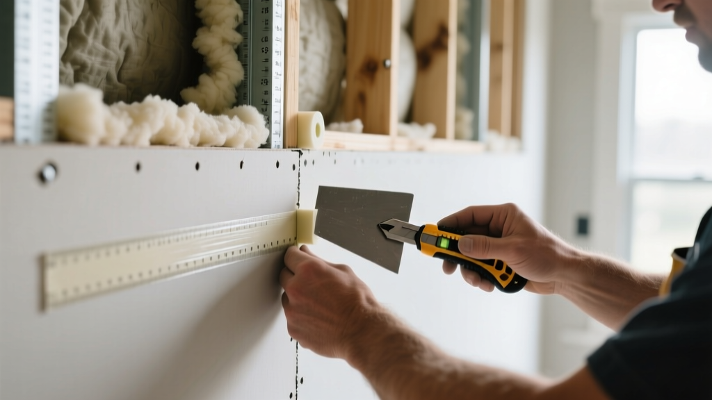
The Physics of Drywall Movement: Why Control Joints are Non-Negotiable
Gypsum board is inherently brittle. When subjected to the natural forces of a building's lifecycle, a continuous monolithic drywall membrane will inevitably fracture. To prevent random, unsightly cracking, installers must introduce planned lines of weakness. This is the exact function of a gypsum board control joint. Unlike structural expansion joints designed for massive seismic shifts, drywall control joints primarily manage three specific forces:
- Hygrometric Shrinkage: Gypsum panels absorb ambient moisture during storage and installation. As the building's HVAC system stabilizes the interior climate, the panels dry out and shrink, creating immense tensile stress across long spans.
- Thermal Expansion and Contraction: Sun-exposed exterior walls and roof decks experience significant temperature deltas, causing the framing and attached drywall to expand and contract daily.
- Structural Deflection: Live loads (occupants, furniture, snow) cause floor joists and roof trusses to deflect slightly, bending the rigid drywall attached to them.
By segmenting large wall and ceiling planes, control joints absorb this kinetic energy, localizing movement to a flexible V-groove rather than allowing it to tear the paper face of the drywall.
Code Requirements and Spacing Rules (The 30-Foot Rule)
Improper spacing is the leading cause of control joint failure. If joints are placed too far apart, the cumulative shrinkage exceeds the joint's articulation capacity. According to the Gypsum Association's GA-216 Application and Finishing guidelines, strict dimensional limits must be observed for both walls and ceilings.
| Parameter | Wall Assemblies | Ceiling Assemblies |
|---|---|---|
| Maximum Distance Between Joints | 30 feet (9.1 m) | 30 feet (9.1 m) |
| Maximum Area Enclosed by Joints | 900 sq. ft. (83.6 m²) | 900 sq. ft. (83.6 m²) |
| Length-to-Width Ratio Limit | Not to exceed 3:1 | Not to exceed 3:1 |
| Alignment with Structural Joints | Mandatory | Mandatory |
Selecting the Right Control Joint Profile
Material science in drywall trims has evolved significantly. While galvanized steel was the mid-century standard, modern construction relies heavily on advanced polymers. Below is a comparison of the three primary profiles used by professional finishers today.
| Material Profile | Popular Models | Articulation Capacity | Best Application |
|---|---|---|---|
| Flexible Vinyl (PVC) | USG Trim-A-Tex, ClarkDietrich 250 | High (absorbs multi-directional shrinkage) | Standard interior walls and ceilings; high-humidity areas. |
| Rigid Zinc / Galvanized Steel | ClarkDietrich Zinc Control Joint | Low (primarily aesthetic reveal) | Commercial corridors, elevator shafts, high-impact zones. |
| Two-Piece Expansion (Tear-Away) | USG Expansion Joint, Trim-Tex Magic Corner | Very High (allows independent lateral movement) | Long commercial hallways, areas spanning structural slab joints. |
For 90% of residential and standard commercial applications, a flexible vinyl profile like the USG Trim-A-Tex Vinyl Control Joint is the optimal choice. It resists denting, will not rust in moist environments, and features a co-extruded flexible hinge that maintains its shape even after multiple coats of joint compound are applied to the flanges.
Step-by-Step Installation Protocol
Executing a flawless control joint requires precision cutting and strict finishing discipline. Follow this sequence to ensure full articulation.
1. Layout and Drywall Cutting
Never attempt to butt two factory edges together and simply screw a trim piece over the seam. You must create a true gap. Measure and cut your gypsum panels so that when they are installed, there is a precise 1/4-inch to 3/8-inch gap between the panel ends. Use a utility knife with a hooked blade to score the back paper, snap the gypsum core, and cut the front paper. Ensure the cut is perfectly plumb or level.
2. Preparing the Joint Cavity
Before inserting the trim, inspect the cavity. Remove any protruding drywall screws, globs of adhesive, or jagged gypsum core fragments. If the framing underneath is continuous wood or steel, some professionals use a router or reciprocating saw to notch out a 1-inch recess in the backing material directly behind the gap. This prevents the backing from restricting the drywall's ability to compress slightly during thermal expansion.
3. Sizing and Fitting the Trim
Cut the vinyl control joint to length using aviation snips or a fine-tooth miter saw. For ceiling-to-wall transitions, cope the ends at 45-degree angles or use pre-molded corner accessories to maintain a continuous flexible hinge line. Press the trim into the gap. The nailing flanges should sit flush against the drywall face without bowing.
4. Fastening the Profile
Secure the control joint using 1-1/4 inch drywall screws or heavy-duty staples. Fasten through the pre-punched holes in the nailing flanges every 6 inches along both sides. Critical distinction: For standard control joints, fasten to both sides of the gap. For two-piece expansion joints with a tear-away strip, fasten only to the primary side, allowing the secondary side to float.
5. Taping and Finishing
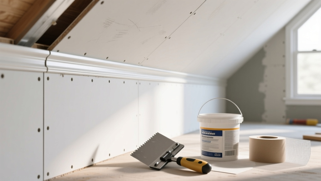
Apply a bedding coat of all-purpose or setting-type joint compound to the nailing flanges. Embed paper tape or fiberglass mesh tape over the flanges if required by the specific trim manufacturer (many modern vinyl trims are designed to be finished without tape, relying on the mechanical grip of the compound on the flange's embossed surface). Apply two to three finishing coats, feathering the edges out 12 to 16 inches to hide the transition.
Never, under any circumstances, allow joint compound to enter the flexible V-groove of the control joint. Mud in the groove will dry rock-hard, effectively turning your control joint into a rigid butt joint and guaranteeing a crack. Use a damp sponge or a specialized V-groove cleaning tool to wipe away any excess compound from the hinge area immediately after each coat.
Troubleshooting Common Installation Failures
Even experienced crews make errors that compromise the integrity of the assembly. Refer to this diagnostic list if you are evaluating a failed drywall system.
- Failure Mode: Diagonal cracking radiating from the joint corners.
Cause: The control joint was not aligned with the structural framing joint, or the drywall panels were forced tightly together without leaving the required 1/4-inch expansion gap inside the trim cavity.
Fix: The drywall must be cut back to relieve the compression, and the joint reset. - Failure Mode: A straight hairline crack running directly down the center of the V-groove.
Cause: Joint compound or primer was allowed to pool and dry inside the flexible hinge, or the back paper of the drywall was left uncut, bridging the gap behind the panels.
Fix: Rout out the hardened compound/paper with a V-groove bit on a rotary tool, clean the cavity, and apply a high-quality elastomeric caulk that matches the ceiling texture. - Failure Mode: Visible ridging or shadowing on the finished surface.
Cause: The nailing flanges were not feathered out sufficiently, or the drywall screws securing the trim were over-driven, crushing the gypsum core and creating a depression.
Fix: Apply a wider skim coat (minimum 18 inches wide) using a lightweight topping compound to blend the transition into the surrounding plane.
FAQ: Edge Cases in Control Joint Placement
Can I use caulk instead of a physical control joint trim?
While elastomeric sealants (like USG First Coat or specialized acoustic sealants) are used in perimeter relief joints where walls meet ceilings, they are not a substitute for a physical control joint in the field of a ceiling or wall. The Association of the Wall and Ceiling Industry (AWCI) explicitly requires manufactured trim profiles for field control joints to ensure consistent width, proper edge protection, and predictable articulation.
Do I need control joints in exterior soffits?
Yes, and the requirements are actually more stringent. Exterior soffits are subject to extreme thermal cycling and wind uplift. Spacing should be reduced to 20 feet maximum, and you must use exterior-rated, UV-stable PVC or zinc trims, as standard interior vinyl will become brittle and degrade under direct sunlight.
How do I handle control joints intersecting with recessed can lights?
Never run a control joint directly through the cutout of a recessed light fixture. The structural integrity of the drywall is already compromised by the cutout, making it a prime location for stress fractures. Offset the control joint by at least 6 inches from any edge of the fixture cutout, or frame out a distinct bulkhead to isolate the lighting zone from the main ceiling plane.
Written by
Marcus ChenMarcus Chen is a licensed structural engineer (PE) and building materials analyst with over 12 years of experience across residential, commercial, and industrial construction. He holds a Master of Science in Civil Engineering from UC Berkeley and spent six years at Thornton Tomasetti before transitioning to independent consulting and technical writing. Marcus specializes in material selection for seismic-prone regions, concrete reinforcement strategies, and lifecycle cost analysis. His work has been cited by the American Concrete Institute (ACI) and the Structural Engineers Association of California (SEAOC). When he is not on a job site or at his desk, you will find him hiking the Sierra Nevada or restoring a 1920s craftsman bungalow in Oakland, CA.
More from Marcus Chen
View all
Construction Cost
How Much Did the Eiffel Tower Cost to Build?
How much did the Eiffel Tower cost to build in 1889? We adjust for inflation and compare its budget to modern skyscraper construction.
Aug 4, 2026

Fire Resistance
What Is a Fire Resistant Material? Testing & Certification Guide
Discover what is a fire resistant material through ASTM and UL testing. Learn how fire ratings, certifications, and assemblies work in construction.
Aug 4, 2026

Construction Cost
How Much Did the Burj Khalifa Cost to Build?
How much did the Burj Khalifa cost to build? We break down the $1.5B project and extract 5 money-saving strategies for your next build.
Jul 30, 2026