Understanding Steel Rebar Sizes: Performance Specs and Grade Ratings
Master steel rebar sizes, ASTM grade ratings, and performance specs. Compare yield strengths, dimensions, and load capacities for structural concrete.
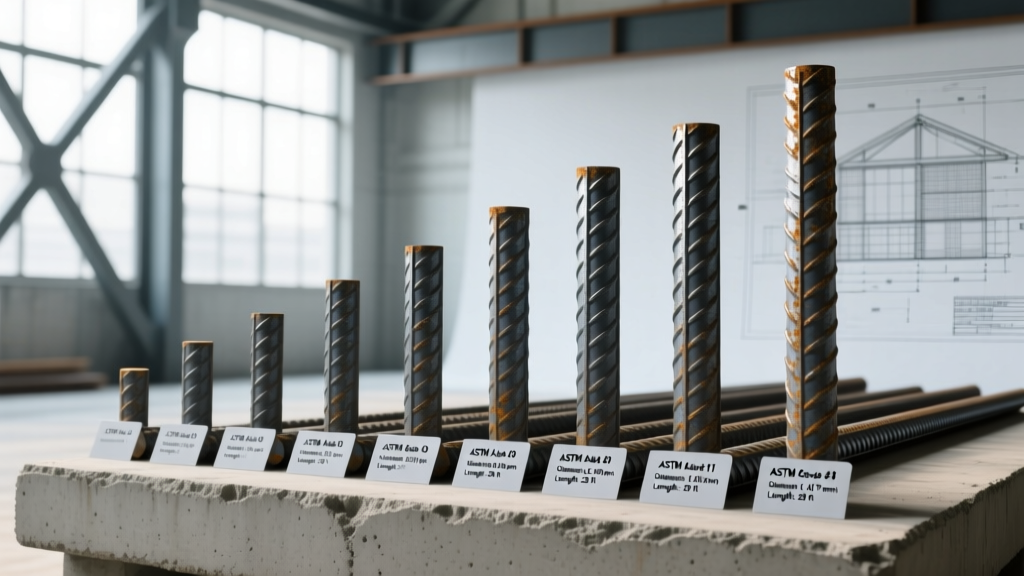
The Anatomy of Steel Rebar Sizes: Beyond the Diameter
Reinforcing steel (rebar) sizing is fundamentally a calculation of cross-sectional area and moment of inertia, not merely a linear diameter measurement. Structural engineers specify steel rebar sizes based on the required tensile capacity to counteract concrete's inherent weakness in tension. While the imperial sizing system uses a number designation (e.g., #4, #5, #8) that historically correlates to the bar's nominal diameter in eighths of an inch, the true structural value lies in the cross-sectional area ($A_s$) and the material's yield strength ($F_y$). Selecting the correct steel rebar sizes requires matching the geometric properties of the bar with the performance ratings dictated by ASTM standards and ACI 318 building code requirements.
Imperial Sizing Matrix: Dimensions and Cross-Sectional Area
The standard imperial sizing framework ranges from #3 (lightweight residential slabs) to #18 (heavy civil infrastructure and high-rise shear walls). The cross-sectional area is the critical metric for calculating the nominal tensile strength ($T_n = A_s imes F_y$) of a reinforced concrete member.
| Bar Size | Nominal Diameter (in) | Cross-Sectional Area (sq in) | Weight (lb/ft) | Typical Application |
|---|---|---|---|---|
| #3 | 0.375 | 0.11 | 0.376 | Residential slabs, light footings |
| #4 | 0.500 | 0.20 | 0.668 | Driveways, standard grade beams |
| #5 | 0.625 | 0.31 | 1.043 | Commercial foundations, retaining walls |
| #6 | 0.750 | 0.44 | 1.502 | Suspended slabs, heavy retaining walls |
| #7 | 0.875 | 0.60 | 2.044 | Bridge decks, heavy-duty columns |
| #8 | 1.000 | 0.79 | 2.670 | High-rise columns, transfer girders |
| #9 | 1.128 | 1.00 | 3.400 | Heavy civil piers, mat foundations |
| #10 | 1.270 | 1.27 | 4.303 | Seismic shear walls, bridge pylons |
| #11 | 1.410 | 1.56 | 5.313 | Massive infrastructure foundations |
| #14 | 1.693 | 2.25 | 7.650 | Special heavy civil, nuclear containment |
| #18 | 2.257 | 4.00 | 13.600 | Dams, specialized heavy-load piers |
Do not assume the 1/8-inch rule applies to #14 and #18 bars. A #14 bar is not 14/8 (1.75) inches; its actual nominal diameter is 1.693 inches. Similarly, a #18 bar is 2.257 inches, not 2.25 inches. These sizes were historically derived from the equivalent cross-sectional area of legacy square twisted bars, not round bar diameter math. Always reference the exact $A_s$ values rather than calculating from assumed diameters.
Performance Ratings: Yield Strength and ASTM Grade Specifications
The physical dimensions of steel rebar sizes are only half of the structural equation. The metallurgical performance rating—specifically the yield strength ($F_y$) and ultimate tensile strength ($F_u$)—determines how much stress the bar can absorb before permanent deformation or rupture.
Standard Carbon Steel: ASTM A615
The ASTM A615 Standard Specification covers deformed and plain carbon-steel bars. The most ubiquitous specification in North America is Grade 60, which mandates a minimum yield strength of 60,000 psi and a minimum tensile strength of 90,000 psi. Grade 75 and Grade 80 are increasingly specified in high-rise construction to reduce steel congestion in heavily loaded columns, allowing engineers to use fewer, larger bars or smaller bars with higher capacity.
Low-Alloy Seismic Steel: ASTM A706
For structures in high seismic design categories (SDC D, E, and F), engineers must specify ASTM A706 low-alloy steel. The critical performance distinction of A706 is its strict control over the strain-hardening ratio. The ultimate tensile strength must be at least 1.15 times the actual yield strength, but no more than 1.45 times the specified yield. This tight window guarantees that the rebar will yield and form a ductile plastic hinge during an earthquake, absorbing seismic energy without experiencing brittle, sudden fracture.
Deformation Geometry and Bond-Slip Failure Modes
Smooth steel bars rely entirely on chemical adhesion and friction to bond with concrete, which fails at very low stress levels. Deformed rebar introduces mechanical interlock via surface ribs. The Concrete Reinforcing Steel Institute (CRSI) and ASTM standards dictate strict geometric tolerances for these deformations to prevent bond-slip failures:
- Rib Height: Must be a minimum of 4% to 5% of the nominal bar diameter, depending on the specific bar size. Undersized ribs lead to premature pull-out under tensile loading.
- Rib Spacing: Cannot exceed 70% of the nominal bar diameter. Wider spacing reduces the bearing area against the concrete, increasing the risk of longitudinal splitting cracks.
- Rib Gap: The gap between the ends of the ribs cannot exceed 12.5% of the nominal perimeter of the bar, ensuring uniform stress distribution around the bar's circumference.
Practical Sizing Framework: Matching Bar Size to Structural Demand
Selecting the optimal steel rebar sizes involves balancing structural capacity with constructability. Over-specifying bar sizes leads to congestion, which prevents concrete aggregate from flowing through the rebar grid, resulting in honeycombing and severe structural weaknesses.
Minimum Spacing and Concrete Consolidation Limits
ACI 318 mandates strict minimum clear spacing between parallel bars to ensure proper concrete vibration and consolidation. The minimum clear spacing must be the greatest of the following three values:
- 1.0 inch (25 mm)
- The nominal diameter of the bar ($d_b$)
- 1.33 times the maximum specified size of the coarse aggregate
Decision Framework: If a column design requires 12 square inches of steel area, using twelve #9 bars ($1.00 sq in$ each) will likely violate spacing limits in a standard 24x24 inch column. Upgrading to eight #11 bars ($1.56 sq in$ each) or utilizing Grade 80 steel reduces the total number of bars, alleviating congestion and ensuring proper concrete encapsulation.
Specification Edge Cases: Coatings and Lap Splices
When specifying steel rebar sizes for corrosive environments (e.g., marine structures, bridge decks exposed to de-icing salts), engineers often mandate epoxy-coated rebar per ASTM A775 or ASTM A934. While the epoxy coating protects the steel from chloride ion penetration, it significantly alters the bar's performance characteristics.
The smooth epoxy layer reduces the mechanical friction and bond strength between the rebar deformations and the surrounding concrete matrix. Consequently, ACI 318 requires a 1.2 multiplier to be applied to the development length ($l_d$) and lap splice lengths for epoxy-coated bars. If you are substituting epoxy-coated #5 bars for uncoated #5 bars in an existing design, you must recalculate the anchorage zones; failing to extend the embedment depth by 20% will result in a premature bond failure at the critical moment connection.
Furthermore, when utilizing larger steel rebar sizes (#11 and above), lap splicing becomes highly inefficient and structurally problematic due to the massive development lengths required and the extreme congestion caused by overlapping thick bars. In these scenarios, performance specifications must transition from lap splices to mechanical couplers (e.g., threaded couplers or grout-filled sleeves) or staggered welded splices to maintain the structural integrity and ductility of the reinforced concrete member.