Steel Roof Framing: Technical Specs, Gauges, and Load Limits
Technical specifications for steel roof framing, including ASTM standards, mil thicknesses, span tables, and structural load limits for modern construction.
Core Material Standards and Metallurgy
Engineering a reliable steel roof framing system requires strict adherence to material standards that govern yield strength, ductility, and corrosion resistance. For cold-formed steel (CFS) roof trusses, rafters, and purlins, the governing material specification in North America is ASTM A1003. This standard dictates the chemical composition and mechanical properties of the steel sheet used to form the framing members.
Key Metallurgical Properties (ASTM A1003)
- Grade 33: Minimum yield strength (Fy) of 33 ksi. Typically used for non-load-bearing partitions or light-duty roof purlins with short spans.
- Grade 50: Minimum yield strength (Fy) of 50 ksi. The industry standard for primary structural roof framing, trusses, and long-span rafters.
- Ductility: Minimum elongation of 10% in 2 inches, ensuring the steel can absorb seismic and high-wind energy without brittle fracture.
Corrosion protection is equally critical, particularly for roof assemblies exposed to high humidity or coastal environments. Galvanization is specified under ASTM A653. For interior, climate-controlled roof cavities, a G60 coating (0.60 oz/ft² total zinc) is generally sufficient. However, for exterior-exposed canopies, unconditioned attics, or coastal projects, engineers must specify G90 (0.90 oz/ft²) to prevent red rust and subsequent section loss over the 50-year design life of the structure.

Section Properties: The Shift from Gauge to Mils
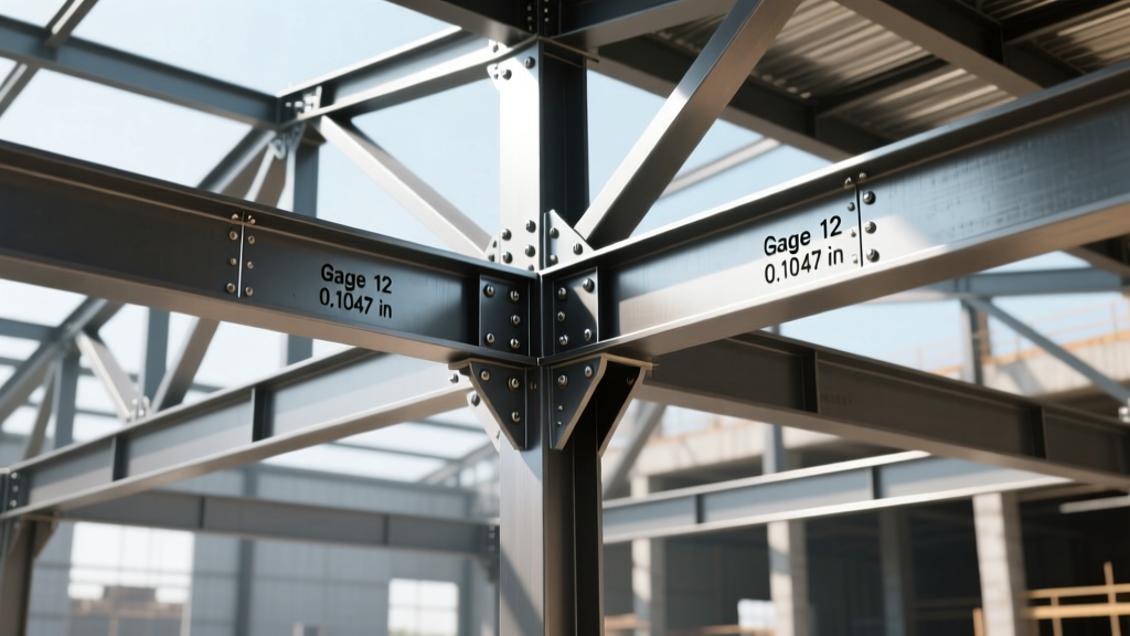
A common error in modern steel roof framing procurement is specifying material by 'gauge' rather than 'mils'. Prior to 2001, gauge numbers (e.g., 20-gauge, 16-gauge) were used to denote thickness. However, because gauge thicknesses varied between manufacturers and materials, the Cold-Formed Steel Engineers Institute (CFSEI) and the American Iron and Steel Institute (AISI) transitioned to specifying design thickness in mils (thousandths of an inch) and millimeters.
| Designation | Min. Thickness (in) | Design Thickness (mils) | Design Thickness (mm) | Typical Roof Application |
|---|---|---|---|---|
| 33 mils (20 ga) | 0.0296 | 33 | 0.84 | Light-duty purlins, furring, non-structural sheathing support |
| 43 mils (18 ga) | 0.0383 | 43 | 1.09 | Residential roof trusses, secondary framing, girts |
| 54 mils (16 ga) | 0.0508 | 54 | 1.37 | Commercial roof rafters, primary truss chords, heavy purlins |
| 68 mils (14 ga) | 0.0646 | 68 | 1.73 | Heavy structural trusses, long-span portal frames, ridge beams |
| 97 mils (12 ga) | 0.0922 | 97 | 2.46 | Primary structural columns, heavy transfer trusses |
When reviewing shop drawings or ordering materials for a steel roof framing project, always verify the design thickness in mils. The minimum thickness represents the bare steel before galvanization, while the design thickness is the value used in all structural calculations per AISI S100.
Structural Load Capacities and Deflection Limits
Roof framing members must be designed to resist a combination of gravity loads (dead and snow) and uplift loads (wind). In steel roof framing, uplift often governs the design of the top chords and the connection details, while gravity governs the bottom chords and overall deflection.
Deflection Criteria
Excessive deflection in steel roof systems leads to ponding water, cracked interior finishes, and compromised roofing membranes. The International Building Code (IBC) and AISC guidelines mandate specific deflection limits:
- Live Load (Snow/Rain): L/240 (where L is the span length). For a 24-foot rafter, maximum deflection under snow load is 1.2 inches.
- Total Load (Dead + Live): L/360. Required when supporting brittle finishes like plaster or tile.
- Wind Uplift: Deflection limits are typically relaxed to L/120 or L/60, as wind is a transient load and roof membranes can accommodate greater movement.
Connection and Fastener Specifications
The structural integrity of a steel roof framing system relies entirely on its connections. Unlike wood framing, which utilizes nails and timber connectors, CFS roof framing utilizes self-drilling, self-tapping steel screws. The selection of the correct fastener is dictated by the shear capacity, pull-over strength, and pull-out strength required at each joint.
Fastener Sizing and Edge Distance
The most common fasteners used in steel roof framing are #8, #10, and #12 hex washer head (HWH) or pancake-head self-drillers. The number denotes the screw diameter:
- #8 Screw: 0.164-inch diameter. Used for connecting 33-mil and 43-mil members (e.g., purlin to truss clip).
- #10 Screw: 0.190-inch diameter. The standard workhorse for 54-mil truss chord connections and rafter-to-top-plate attachments.
- #12 Screw: 0.210-inch diameter. Reserved for heavy structural connections, splice plates, and 68-mil+ members.
Per AISI S100 Chapter E, the minimum edge distance from the center of the fastener to the edge of the steel member must be at least 1.5 times the fastener diameter (1.5d). For a #10 screw, this means the center of the screw must be at least 0.285 inches from the edge of the stud or track flange. Failing to maintain this edge distance drastically reduces the tear-out capacity of the connection.
Pull-Over vs. Pull-Out Failure
When designing roof uplift connections (such as truss heel joints), engineers must calculate both pull-over and pull-out capacities. Pull-out occurs when the screw threads strip the base metal. Pull-over occurs when the screw head tears through the top sheet of steel. In thin-gauge roof framing (33 to 43 mils), pull-over almost always governs the design. To increase pull-over capacity without upsizing the steel, contractors should specify screws with oversized washer heads (e.g., 5/8-inch or 3/4-inch diameter washers) rather than standard 3/8-inch hex heads.
Bracing and Lateral Torsional Buckling (LTB)
Steel roof rafters and truss chords are highly susceptible to Lateral Torsional Buckling (LTB) under compressive loads. Because CFS members are open sections (C-shapes or U-shapes), they have very low torsional rigidity. If the compression flange is not adequately braced, the member will twist and fail at a fraction of its calculated yield strength.
Bracing Strategies
To prevent LTB, the compression flange must be braced at regular intervals. The required bracing spacing is calculated based on the unbraced length (Lb) and the radius of gyration (ry) of the section.
- Continuous Bracing: Achieved by attaching structural roof sheathing (e.g., 5/8-inch OSB or plywood) directly to the top flange of the rafters or trusses using #8 screws at 6-inch to 12-inch on-center spacing. This effectively reduces the unbraced length of the top flange to zero.
- Discrete Bracing: Used when sheathing cannot be attached directly to the compression flange (e.g., in bottom chords of trusses where the ceiling drywall provides inadequate lateral resistance). Steel strap bracing (typically 1.5-inch wide, 33-mil flat straps) or proprietary clip-and-rod systems are installed in an X-pattern between trusses at intervals not exceeding 8 feet.
Common Failure Modes: Web Crippling
One of the most frequent failure modes in steel roof framing occurs at the bearing points—specifically where rafters rest on top tracks or where concentrated loads are applied to the web of a C-section. This localized failure is known as web crippling.
When a vertical reaction force pushes against the flange of a C-section, the thin web (often only 54 mils thick) can buckle or fold inward. AISI S100 Chapter G provides complex equations to calculate web crippling capacity based on the ratio of the bearing length (N) to the web height (h). If the calculated reaction force exceeds the web crippling capacity, the framing member will fail even if the overall bending and shear capacities are adequate.
Mitigating Web Crippling in Roof Framing
- Web Stiffeners: Install C-shaped stiffener sections back-to-back with the main rafter at all bearing points, fastened with #10 screws at 2-inch spacing.
- Clip Angles: Use heavy-gauge (68 mil or 97 mil) L-shaped clip angles to transfer the load directly from the rafter web to the supporting structure, bypassing the flange-to-web bend radius.
- Bearing Length Extension: Increase the bearing length (N) by using wider top plates or continuous structural tracks, which distributes the reaction force over a larger area of the web.
By strictly adhering to these technical specifications, structural engineers and framing contractors can ensure that steel roof systems perform reliably under extreme environmental loads while optimizing material usage and project costs.
Written by
Priya KapoorPriya Kapoor is a real estate market analyst and construction economics researcher with expertise in housing affordability, development feasibility, and infrastructure investment. She holds a Master of Regional Planning from Cornell University and previously worked as a senior analyst at CBRE's Investment Properties group, where she modeled returns for $4B in mixed-use development pipelines. Priya now runs an independent research practice advising developers, municipalities, and REITs on construction cost forecasting and market timing. She publishes the quarterly "BuildMat Market Pulse" report tracking material price indices across 12 commodity categories. Based in Austin, TX, Priya serves on the board of Habitat for Humanity Austin and is a marathon runner.
More from Priya Kapoor
View all
Construction Cost
Cost to Build a 1600 Sq Ft Home in 2026: Full Breakdown
Accurate 2026 cost to build a 1600 sq ft home—material, labor, and regional pricing breakdowns included. Plan your budget with real-time estimates.
Aug 11, 2026
Wood & Lumber
Name the Types of Wood for Pressure Treatment and Preservation
Learn how to name the types of wood best suited for pressure treatment. Compare species treatability, chemical retention levels, and 2026 preservation costs.
Aug 4, 2026

Stone & Masonry
Stone Veneer Suppliers Lindenhurst: 2026 Cost Analysis
Analyze 2026 stone veneer costs in Lindenhurst, NY. Compare local supplier pricing, delivery fees, and Suffolk County installation labor rates.
Aug 4, 2026