Installing Wire Mesh Rebar: Concrete Slab Reinforcement Guide
Master wire mesh rebar installation for concrete slabs. Learn exact chair spacing, lapping overlaps, cutting techniques, and ASTM WWR standards.
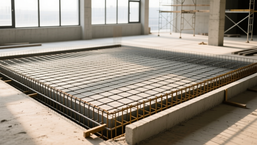
The Terminology: Wire Mesh vs. Traditional Rebar
In structural engineering and flatwork, the term 'wire mesh rebar' is a colloquialism for Welded Wire Reinforcement (WWR). While traditional rebar (ASTM A615) consists of individual, deformable steel bars tied together on-site, WWR (ASTM A1064) is factory-welded into rigid grids. WWR provides superior crack-width control in slabs-on-grade due to its closely spaced, continuous cross-wires, which distribute tensile stresses more evenly than widely spaced #4 or #5 rebar.
According to the Portland Cement Association, WWR is the preferred reinforcement method for residential driveways, warehouse floors, and light commercial slabs where controlling shrinkage and temperature cracking is the primary objective. However, it does not replace structural rebar in deep footings, suspended slabs, or heavy-load transfer beams.
Material Specifications and Selection Matrix
Selecting the correct wire mesh rebar gauge is critical. WWR is designated by the W-number system, which indicates the cross-sectional area of the wire in hundredths of a square inch. The most common grid spacing is 6x6 inches.
| WWR Designation | Imperial Gauge | Wire Diameter | Primary Application | Approx. Cost per 150 sq ft Sheet |
|---|---|---|---|---|
| 6x6 W1.4 x W1.4 | 10-Gauge | 0.135 inches | Sidewalks, patios, light residential flatwork | $35 - $45 |
| 6x6 W2.9 x W2.9 | 6-Gauge | 0.192 inches | Driveways, garage floors, light commercial | $75 - $95 |
| 6x6 W4.0 x W4.0 | 4-Gauge | 0.225 inches | Heavy equipment pads, industrial warehouse floors | $110 - $140 |
Note: Pricing reflects early 2026 stabilized steel market rates. Galvanized or epoxy-coated WWR will carry a 20% to 35% premium over standard carbon steel.
Pre-Pour Preparation: Subgrade and Vapor Barriers
Wire mesh rebar cannot compensate for a poorly prepared subgrade. Before unrolling or placing sheets of WWR, ensure the following:
- Compaction: The subgrade must be compacted to a minimum of 95% Standard Proctor density. Uneven settling will cause the slab to snap, regardless of the steel reinforcement.
- Vapor Barrier: Install a continuous 10-mil or 15-mil polyethylene vapor retarder directly beneath the mesh (over a 2-inch sand blinding layer if the subgrade is sharp aggregate). This prevents moisture migration and protects the mesh from direct soil contact, which accelerates corrosion.
Step-by-Step Wire Mesh Rebar Installation Procedure
Proper elevation and positioning of the mesh dictate its effectiveness. In a slab-on-grade, the bottom of the slab is in compression, while the top surface experiences tension when loaded. Therefore, the wire mesh must be positioned in the upper third of the slab thickness.
Step 1: Cutting and Sizing
Standard WWR sheets are typically 5 feet wide by 15 feet long (150 square feet). Cut sheets to fit the forming using heavy-duty bolt cutters for 10-gauge and 6-gauge mesh. For 4-gauge or thicker, use an angle grinder equipped with a Type 1 metal cutoff wheel. Always wear ANSI Z87.1-rated eye protection and heavy leather gloves, as cut wire ends are razor-sharp and under tension.
Step 2: Setting the Chairs (Bolsters)
Never lay wire mesh directly on the vapor barrier or dirt. Use concrete-tipped plastic bar chairs or continuous concrete bolsters.
- For a 4-inch slab: Use 1.5-inch to 2-inch high chairs to place the mesh in the upper third.
- For a 6-inch slab: Use 3-inch to 4-inch high chairs.
- Spacing: Place chairs on a 3-foot by 3-foot grid. Under heavy wheel traffic during the pour, reduce spacing to 2 feet to prevent the mesh from collapsing to the subgrade.
Step 3: Placing and Tying
Lay the WWR sheets over the chairs. Where sheets overlap, they must be tied securely to prevent the grid from buckling upward when wet concrete is struck off. Use 16-gauge black annealed tie wire, twisting it tightly with pliers at every other intersection in the lap zone.
Many amateur contractors lay the mesh flat on the ground and attempt to 'pull it up' through the wet concrete with rakes or hooks during the pour. This is explicitly prohibited by ACI 318 and local building codes. Pulling the mesh ruins the subgrade vapor barrier, creates voids beneath the steel, and almost always results in the mesh ending up in the bottom half of the slab where it provides zero tensile resistance to surface cracking.
Lapping, Splicing, and Edge Clearances
According to guidelines published by the Wire Association International, proper lapping ensures continuous load transfer across sheet boundaries.
- Minimum Lap Length: Sheets must overlap by a minimum of 6 inches, OR one full mesh spacing plus 2 inches (whichever is greater). For a standard 6x6 grid, the minimum lap is 8 inches.
- Edge Clearances: Maintain a minimum of 2 inches of concrete cover from the edge of the slab to the end of the wire mesh. For exterior slabs exposed to de-icing salts or marine environments, increase this clearance to 3 inches to prevent rust-jacking, where expanding corrosion spalls the concrete edge.
Integrating Wire Mesh with Control Joints
A frequent and catastrophic installation error is allowing wire mesh rebar to cross control joints (saw cuts or tooled grooves). Control joints are designed to create a plane of weakness, forcing the concrete to crack in a straight, hidden line as it shrinks. If continuous WWR crosses this joint, the steel holds the concrete together, building up immense internal tension until the slab cracks randomly outside the joint.
The Fix: You must physically cut the wire mesh at every control joint line. If using saw-cut joints, install the mesh continuously, but ensure the saw blade depth (typically 25% of slab depth) does not cut into the steel. If the mesh is in the upper third of a 4-inch slab (approx. 1.5 inches down), a 1-inch saw cut will safely clear the steel. For tooled joints, cut the mesh with bolt cutters directly beneath the joint line before the pour.
Common Installation Failure Modes and Troubleshooting
| Failure Symptom | Root Cause | Corrective Action / Prevention |
|---|---|---|
| Rust stains bleeding through the finished surface | Insufficient top cover; mesh was pushed too high during finishing. | Maintain minimum 1-inch top cover. Use rigid concrete bolsters instead of flimsy plastic chairs that collapse underfoot. |
| Random map-cracking despite reinforcement | Mesh placed in the bottom third of the slab; improper curing. | Verify chair heights before the pour. Implement wet-curing or spray-on curing compounds immediately after finishing. |
| Cracks crossing control joints at 45-degree angles | Wire mesh was not cut at the joint line, bridging the gap. | Cut the WWR grid completely at all isolation and control joint locations prior to pouring. |
When to Use Wire Mesh vs. Fiber Reinforcement
While macro-synthetic fibers are increasingly popular for secondary shrinkage reinforcement, they do not replace wire mesh rebar in structural applications. Fibers control plastic shrinkage cracking during the first 24 hours of curing. WWR provides long-term structural tensile strength, bridging cracks that occur months or years later due to thermal cycling and subgrade shifting. For high-performance driveways and warehouse floors in 2026, the industry best practice is a hybrid approach: utilizing both WWR for structural reinforcement and a low-dose synthetic fiber mix to eliminate early-age plastic shrinkage.