Concrete Slab vs Foundation: Technical Specs & Load Paths
Compare concrete slab-on-grade vs deep foundation systems. Technical specs, rebar sizing, PSI requirements, and IRC code load paths for 2026 builds.

The Engineering Distinction: Slab-on-Grade vs. Deep Foundations
In structural engineering and residential construction, the phrase "concrete slab vs foundation" represents a category error. A concrete slab-on-grade is a foundation system. The actual technical comparison is between slab-on-grade systems (monolithic or supported) and deep/traditional foundations (T-shaped footings, stem walls, and pier-and-beam configurations). The choice between these systems dictates the load path, frost heave resistance, and differential settlement tolerance of the entire structure.
According to the International Residential Code (IRC) Chapter 4, foundation selection is strictly governed by local soil bearing capacity, frost line depth, and seismic risk. This guide details the exact technical specifications, material requirements, and failure modes for both systems to inform structural design and material procurement.
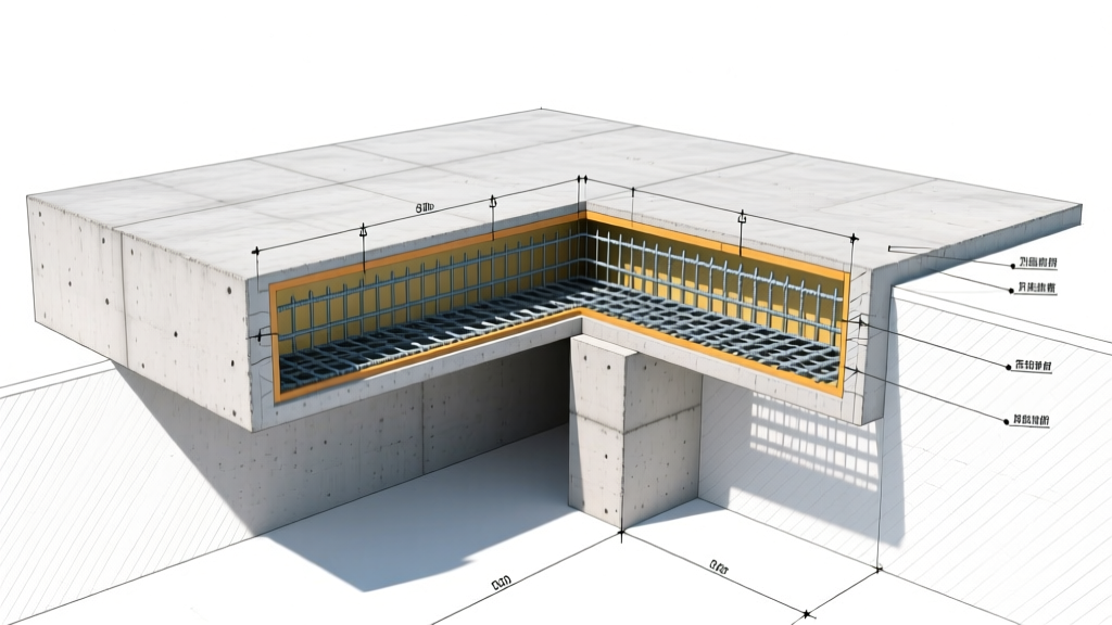
Technical Specifications: Slab-on-Grade Systems
Slab-on-grade foundations transfer structural loads directly to the underlying soil through a continuous concrete plane. They are divided into two primary engineering categories: monolithic (Alaska) slabs and supported slabs with stem walls.
Monolithic Slabs (Thickened-Edge)
Monolithic slabs are poured in a single continuous operation, integrating the floor and the perimeter footing. They are restricted to regions with shallow frost lines or expansive soils where deep footings are structurally unfeasible without extensive over-excavation.
- Interior Thickness: 4.0 inches minimum (5.0 inches for concentrated point loads exceeding 1,000 lbs).
- Perimeter Footing: 12 inches deep by 24 inches wide minimum.
- Concrete Compressive Strength: 3,000 psi minimum at 28 days.
- Reinforcement: #4 (1/2-inch) Grade 60 rebar placed continuously in the thickened edge, plus 6x6 W2.9xW2.9 welded wire reinforcement (WWR) in the slab field.
Post-Tensioned Slabs for Expansive Soils
In regions with high-plasticity clay (e.g., Texas, Colorado), standard rebar is insufficient to prevent cracking from soil swelling. Post-tensioned (PT) slabs utilize 270 ksi low-relaxation steel strands encased in grease-filled plastic sheathing. After the concrete reaches 3,000 psi (typically 7-10 days), strands are stressed to 33,000 lbs using hydraulic jacks, placing the entire slab into active compression. This neutralizes tensile stresses caused by differential soil movement.
Vapor Retarder Specifications
Moisture migration through concrete is a primary cause of flooring adhesive failure and indoor air quality degradation. The 2021 IRC mandates a Class I vapor retarder (<= 0.1 perm rating) directly beneath the slab. Standard 6-mil polyethylene is no longer considered adequate by structural engineers due to high puncture rates during rebar tying. Current best practice specifies a 15-mil polyolefin membrane (e.g., Stego Wrap) compliant with ASTM E1745, which maintains a perm rating of <= 0.01 even after sub-slab abrasion.
Technical Specifications: Deep & T-Shaped Foundations
Deep foundations separate the structural floor from the earth, utilizing continuous footings placed below the local frost line to transfer loads to stable, undisturbed soil strata. This system is mandatory in Climate Zones 5 through 8, where frost penetration exceeds 32 inches.
Footing and Stem Wall Requirements
A standard T-shaped foundation requires three distinct concrete pours: the footing, the stem wall, and the interior slab (which is structurally isolated from the stem wall to prevent frost-jacking).
- Footing Depth: Minimum 12 inches below undisturbed soil, and strictly below the local frost line (e.g., 48 inches in Chicago, 36 inches in Philadelphia).
- Footing Dimensions: 24 inches wide by 8 inches thick minimum for 2-story wood-frame structures on soils with a 2,000 psf bearing capacity.
- Stem Wall: 8-inch minimum thickness, reinforced with #5 (5/8-inch) vertical rebar at 48 inches on-center, tied to #4 horizontal rebar at the top and bottom courses.
- Concrete Mix: Air-entrained mix (4% to 7% air content per ASTM C457) is mandatory for any concrete exposed to freeze-thaw cycles to prevent spalling and scaling.
"When designing for freeze-thaw durability, the air-void system in the concrete matrix is more critical than the compressive strength. A 4,000 psi mix without proper air entrainment will disintegrate faster in northern climates than a 2,500 psi mix with a 6% air content." — Portland Cement Association (PCA)
Load Path Mechanics & Soil Bearing Matrix
The fundamental difference between a slab-on-grade and a deep foundation is the soil bearing interaction. Slabs rely on the uniform bearing capacity of the top 12 inches of engineered fill, while deep foundations bypass weak surface soils to bear on deeper, compacted strata.
| Soil Type (USCS) | Presumptive Bearing Capacity (psf) | Recommended Foundation System | Settlement Risk |
|---|---|---|---|
| Bedrock / Soft Rock | 12,000 | Monolithic Slab | Negligible |
| Gravel / Sandy Gravel (GW, GP) | 3,000 - 4,000 | Slab or T-Footing | Low |
| Silt / Silty Clay (ML, CL) | 1,500 - 2,000 | Deep T-Footing / Pier | Moderate to High |
| Expansive Clay (CH) | 1,500 (Variable) | Post-Tensioned Slab / Drilled Piers | Extreme (Differential) |
Failure Modes: Differential Settlement and Frost Heave
Understanding the specific failure modes of each system is critical for long-term structural integrity and warranty mitigation.
Slab-on-Grade Failure: Edge Curling and Moisture Wicking
The most common technical failure in slab-on-grade systems is edge curling. This occurs when the top surface of the concrete dries and shrinks faster than the bottom surface, which is trapped against the vapor retarder. To mitigate curling, engineers specify a maximum water-to-cement (w/c) ratio of 0.45 and utilize synthetic macro-fibers (e.g., 3 lbs per cubic yard of polypropylene) to control plastic shrinkage cracking. Furthermore, if the capillary break (usually 4 inches of washed gravel) is omitted beneath the vapor barrier, hydrostatic pressure will force moisture through micro-cracks, destroying epoxy floor coatings and hardwood adhesives.
Deep Foundation Failure: Frost Jacking and Lateral Soil Pressure
In deep foundations, the primary failure mode is frost jacking. If the concrete stem wall or pier is poured against rough, unformed earth in clay soils, freezing moisture will adhere to the concrete surface and lift the foundation upward during winter thaw-freeze cycles. The technical fix requires applying a 2-inch layer of rigid extruded polystyrene (XPS) insulation or a specialized slip-plane membrane to the exterior of the stem wall to eliminate skin friction. Additionally, poorly drained backfill against stem walls exerts lateral hydrostatic pressure, leading to inward bowing and horizontal shear cracking if the wall lacks adequate horizontal rebar or pilasters.
Code-Driven Decision Framework
Selecting between a slab-on-grade and a deep foundation requires a systematic evaluation of site-specific variables. Use the following decision matrix based on FEMA Building Science guidelines and local geotechnical reports:
➔ Specify: Monolithic Slab-on-Grade with thickened edges.
IF the local frost depth exceeds 32 inches OR the site features poorly drained silts:
➔ Specify: Deep T-Shaped Foundation with continuous footings below the frost line.
IF the geotechnical report identifies high-plasticity expansive clays (PI > 25):
➔ Specify: Post-Tensioned Slab OR Drilled Concrete Piers with a suspended structural slab.
IF the site is located in a high-seismic risk zone (SDC D, E, or F):
➔ Specify: Deep foundation with grade beams tying all isolated footings together to prevent lateral displacement during shear wave propagation.
Ultimately, the choice is not a matter of preference but of strict geotechnical compliance. Procurement teams must ensure that concrete batch tickets verify the specified PSI, slump, and air-entrainment percentages upon delivery, as field-modifying concrete with excess water to improve workability will catastrophically compromise the structural load path and void all engineering warranties.
Written by
James ThorntonJames Thornton is a construction industry veteran with 25 years of hands-on experience in wood framing, lumber grading, and residential building codes. He started as a framing carpenter in rural Oregon, earned his ICC Residential Building Inspector certification, and eventually became a senior plan reviewer for the City of Portland Bureau of Development Services. James holds a B.S. in Wood Science & Technology from Oregon State University and is a certified lumber grader through the West Coast Lumber Inspection Bureau (WCLIB). He has inspected over 3,000 residential construction sites and authored the city's internal guide on advanced framing techniques (2x6 at 24" O.C.). James lives in Bend, OR, where he builds custom timber-frame cabins and competes in lumberjack sports.
More from James Thornton
View all
Insulation
Best Home Insulation Materials: Complete 2026 Guide
Compare top home insulation materials for 2026. Find R-values, installed costs per square foot, and best uses for fiberglass, spray foam, and mineral wool.
Aug 4, 2026

Sustainable Building
Certify Your Green Building Material for LEED and WELL
Step-by-step guide to certifying a green building material for LEED v5 and WELL v2. Master EPDs, HPDs, and VOC limits for 2026 project specifications.
Aug 4, 2026

Stone & Masonry
Veneer Stacked Stone Panels: Interior Design & Style Showcase
Discover how veneer stacked stone panels transform interiors. Explore modern design profiles, material pairings, and technical installation specs.
Aug 4, 2026