Poured Concrete Wall Retaining Systems: Installation Guide
Master poured concrete wall retaining installation with our step-by-step guide covering formwork, rebar spacing, drainage, and curing times.
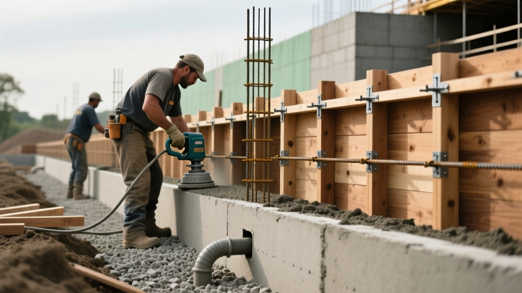
Site Preparation and Excavation Tolerances
Engineering a cast-in-place concrete wall retaining structure begins long before the first yard of concrete is poured. The structural integrity of the wall relies entirely on the load-bearing capacity of the subgrade and the precise dimensions of the continuous footing. For walls exceeding 4 feet in height, geotechnical soil testing is mandatory to determine the allowable bearing pressure, typically requiring a minimum of 2,000 to 3,000 pounds per square foot (psf) for standard residential applications.
Excavation must extend below the local frost line to prevent frost heave from compromising the footing. In northern climates, this means trenching 36 to 48 inches deep. The trench bottom must be compacted to 95% Standard Proctor density. If the subgrade consists of expansive clay or organic material, it must be over-excavated by 12 inches and replaced with a compacted engineered fill, such as 3/4-inch crushed aggregate base.
Formwork Engineering and Rebar Placement
Formwork for concrete wall retaining systems must withstand immense lateral fluid pressure during the pour. Standard 3/4-inch plywood backed by 2x4 studs at 12-inch centers and double 2x6 wales is the minimum requirement for walls up to 8 feet high. Use snap ties with plastic cones spaced no more than 24 inches apart vertically and horizontally to secure the opposing form faces.
Reinforcement steel (rebar) is non-negotiable for retaining walls, as concrete possesses high compressive strength but negligible tensile strength. The vertical rebar must be dowelled into the footing using epoxy anchoring systems or cast-in-place J-bars, extending up into the wall with a minimum 40-bar-diameter lap splice length.
Rebar Sizing and Spacing Matrix
| Wall Height | Wall Thickness | Vertical Rebar | Horizontal Rebar | Spacing (O.C.) |
|---|---|---|---|---|
| Up to 4 ft | 8 inches | #4 (1/2 in) | #4 (1/2 in) | 24 inches |
| 4 ft to 6 ft | 8 to 10 inches | #5 (5/8 in) | #4 (1/2 in) | 18 inches |
| 6 ft to 8 ft | 10 to 12 inches | #6 (3/4 in) | #5 (5/8 in) | 12 inches |
Note: Always consult a licensed structural engineer for walls exceeding 4 feet, as local building codes and specific soil surcharges (like driveways or pools near the top of the wall) will dictate exact reinforcement requirements per ACI 318 Building Code Requirements.
Critical Drainage Integration
Hydrostatic pressure is the primary cause of retaining wall failure. Water trapped behind the wall exerts approximately 62.4 pounds of lateral force per cubic foot, compared to roughly 45 pounds per cubic foot for dry soil. A comprehensive drainage system must be integrated during the formwork and backfill stages.
- Perforated Pipe: Install a 4-inch Schedule 40 PVC perforated pipe at the base of the wall, directly on top of the footing, behind the rebar cage. Ensure the pipe maintains a minimum 1% slope (1/8 inch per foot) to daylight or a dry well.
- Filter Fabric: Wrap the drain pipe and the entire backfill zone in a non-woven geotextile fabric (minimum 4 oz per square yard) to prevent fine soil particles from migrating into the drain rock and clogging the system.
- Drain Rock: Backfill the immediate 12-inch zone directly behind the wall with 3/4-inch washed clear crushed stone. Do not use gravel with fines (like crusher run), as it will not drain effectively.
- Weep Holes: For walls over 6 feet, install 2-inch PVC weep holes through the formwork every 8 feet horizontally, positioned 12 inches above the finished grade.
The Concrete Pour: Mix Design and Execution
The concrete mix design for retaining walls must balance high compressive strength with workability. Request a 4,000 PSI mix with a maximum 3/4-inch aggregate size. Because retaining walls are exposed to the elements, the mix must include 5% to 7% air entrainment to resist freeze-thaw scaling, a standard detailed by the Portland Cement Association's durable concrete guidelines.
Maintain a strict 4-inch to 5-inch slump. Never allow the ready-mix truck driver to add water at the job site to increase workability. Excess water increases the water-cement ratio, drastically reducing compressive strength and increasing shrinkage cracking. If higher flowability is needed, request a high-range water reducer (superplasticizer) from the batch plant.
During the pour, place concrete in maximum 18-inch to 24-inch lifts. Use a mechanical internal vibrator (pencil vibrator) to consolidate the concrete. Insert the vibrator every 18 inches, penetrating 6 inches into the previous lift to eliminate cold joints and honeycombing. Do not over-vibrate, as this will cause the aggregate to settle at the bottom and bleed water to the top.
Waterproofing and Dampproofing Membranes
Once the forms are stripped (typically 24 to 48 hours post-pour), the earth-facing side of the wall must be treated before backfilling. For walls protecting habitable spaces (like basements), a full waterproofing membrane (such as a peel-and-stick rubberized asphalt or fluid-applied polyurethane) is required. For standard landscape retaining walls, a heavy-duty damp-proofing coating, such as an asphalt-based foundation coating applied at a rate of 1 gallon per 100 square feet, is sufficient to prevent moisture migration and protect the concrete from soil chemicals.
Apply a dimpled high-density polyethylene (HDPE) drainage mat over the waterproofing layer. This mat protects the membrane from backfill abrasion and creates an air gap that channels water rapidly down to the footing drain.
Curing, Stripping, and Backfilling Protocols
Concrete achieves its structural strength through hydration, which requires moisture and time. Immediately after stripping the forms, apply a spray-on liquid curing compound or wrap the exposed concrete in wet burlap covered with 4-mil polyethylene sheeting for a minimum of 7 days.
Backfilling Rules: Do not begin backfilling against the wall until the concrete has cured for at least 7 days, or has reached 70% of its design compressive strength (verified via field-cured cylinder breaks). Backfill must be placed in 8-inch lifts and compacted using a walk-behind plate compactor. Never use heavy, ride-on vibratory rollers near the wall face, as the dynamic lateral loads can push the wall out of plumb or cause catastrophic overturning before the wall's base is fully locked in.
Common Failure Modes and Prevention Matrix
Understanding how concrete wall retaining systems fail allows contractors to implement preventative measures during installation.
| Failure Mode | Primary Cause | Installation Prevention Protocol |
|---|---|---|
| Overturning | Insufficient footing heel/toe ratio or extreme surcharge loads. | Ensure the footing extends at least 2/3 of its width behind the wall face (heel) and 1/3 in front (toe). |
| Sliding | Poor subgrade friction or lack of a shear key. | Form a 6-inch deep by 8-inch wide shear key beneath the footing to lock into the undisturbed subgrade. |
| Bowing / Shear Cracking | Hydrostatic pressure buildup or undersized rebar. | Verify drain pipe daylighting and strictly adhere to the engineered rebar spacing matrix. |
| Surface Scaling | Lack of air entrainment or premature finishing. | Reject loads without 5-7% air entrainment; never trowel bleed water back into the surface. |
By adhering to these strict installation tolerances, mix designs, and drainage protocols, contractors can deliver concrete wall retaining structures that remain plumb, crack-free, and structurally sound for decades. Always pull local permits and schedule municipal inspections at the footing, rebar, and final backfill stages to ensure code compliance.