Steel vs Concrete Piers: Troubleshooting Foundation Settlement
Compare steel vs concrete piers for foundation repair. Troubleshoot settlement issues, choose the right underpinning method, and fix structural damage.

Diagnosing the Root Cause of Differential Settlement
When a structure exhibits stair-step cracking in masonry, diagonal fissures radiating from window lintels, or doors that bind in their frames, the culprit is almost always differential settlement. Before debating the merits of steel vs concrete underpinning systems, a forensic approach to the soil-structure interaction is mandatory. Settlement is rarely a uniform event; it is a localized failure of the soil's bearing capacity or a reaction to moisture-induced volumetric changes.
- Cracks wider than 1/4 inch (6mm) that taper from top to bottom.
- Gaps separating the frieze board from the brick veneer.
- Slab heaving resulting in a measurable slope exceeding 1 inch per 20 feet (L/240 deflection limit).
To troubleshoot effectively, structural engineers rely on geotechnical borings to identify the depth of the active soil zone. In regions with highly expansive clays, the active zone can extend 8 to 15 feet below grade. This depth dictates whether a friction-based system or an end-bearing system is required to permanently arrest the settlement.
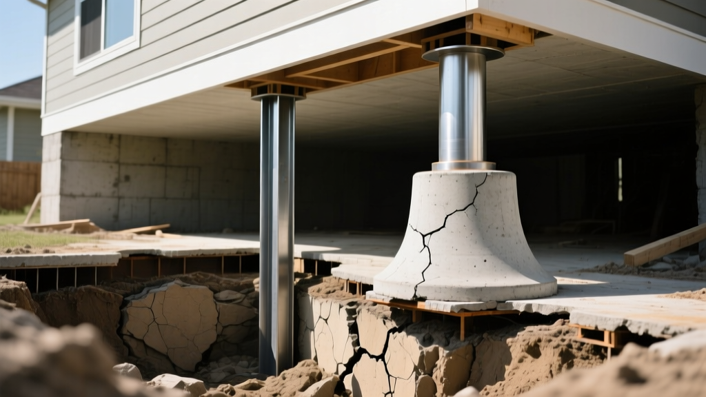
The Core Engineering Divide: End-Bearing vs. Friction
The fundamental difference in the steel vs concrete pier debate lies in load transfer mechanics. Understanding this distinction is the key to selecting the correct repair strategy.
Steel Push Piers (End-Bearing Systems)
Steel push piers utilize high-strength, seamless steel tubing (typically 2 7/8-inch or 3.5-inch outer diameter with a minimum 50 ksi yield strength). They are hydraulically driven through unstable surface soils until they refuse on a load-bearing stratum, such as bedrock or dense glacial till. According to guidelines published by the American Institute of Steel Construction (AISC), the load is transferred directly to this stable stratum, completely bypassing the active, moisture-fluctuating soils. This makes them an end-bearing system.
Drilled Concrete Piers (Friction Systems)
Concrete piers, often referred to as bell-bottom or drilled piers, are created by augering a 10 to 12-inch diameter hole to depths of 10 to 15 feet. The base is belled out to 24 inches, reinforced with a steel rebar cage, and filled with 3,000 psi concrete. As detailed in the American Concrete Institute (ACI) standards, these piers rely on skin friction (the shear strength between the concrete surface and the surrounding soil) and the bearing area of the bell to support the structural load. They do not typically reach bedrock.
Underpinning Comparison Matrix
| Metric | Steel Push Piers | Drilled Concrete Piers |
|---|---|---|
| Load Transfer | End-bearing (Bedrock/Stable Stratum) | Skin friction & Bell bearing |
| Typical Depth | 20 to 60+ feet | 8 to 15 feet |
| Installation Method | Hydraulic ram (vibration-free) | Mechanical auger (soil removal) |
| Lifting Capability | High (can actively lift structure) | Low (primarily stabilizes/arrests) |
| 2026 Avg. Cost per Pier | $1,800 - $2,800 | $900 - $1,500 |
Troubleshooting Specific Soil Failure Modes
Choosing the wrong pier type for your specific soil pathology will result in a failed repair. Here is how to troubleshoot the two most common culprits of foundation distress.
Scenario A: Expansive Montmorillonite Clays
Montmorillonite clays can swell up to 15% in volume when wet and shrink drastically during droughts. If a structure is built on this soil, concrete friction piers are highly vulnerable to negative skin friction. When the soil dries and shrinks, it pulls away from the concrete shaft, eliminating the friction holding the pier up. Furthermore, when the soil re-wets, it swells and grips the concrete shaft, pulling the pier upward (upheaval). Solution: Steel push piers are mandatory here. Because they bypass the active clay zone and bear on bedrock, they are entirely immune to the volumetric changes of the surface clay.
Scenario B: Poorly Compacted Fill Soil
In newer developments where hillsides were leveled, deep layers of uncompacted fill soil can compress over time under the weight of the house. If the fill layer is only 6 to 8 feet deep, drilled concrete piers can be socketed into the natural, undisturbed soil below the fill, providing excellent friction and bearing. Solution: Concrete bell-bottom piers are highly effective and cost-efficient in this scenario, provided the natural soil stratum has adequate shear strength.
Step-by-Step: The Installation Reality
Understanding the installation process helps contractors and homeowners anticipate site disruption and timeline requirements.
- Site Preparation: For both systems, soil is excavated by hand at the foundation footing to expose the bearing ledge. Steel pier installations require smaller work pits (approx. 3x3 feet) compared to the larger equipment footprint needed for concrete auger rigs.
- Pier Advancement: Steel piers are driven using the weight of the structure itself as reaction force. Concrete piers require drilling, which removes soil and can temporarily destabilize the surrounding footing if not cased properly.
- Load Testing: A critical troubleshooting step often skipped by budget contractors. Steel piers are load-tested to 1.5 times the working load during driving to verify bedrock refusal. Concrete piers rely on the 7-day or 28-day compressive strength of the concrete mix, requiring a waiting period before the structure can be fully loaded.
- Lifting and Lock-off: Hydraulic jacks lift the foundation back toward its original elevation. Steel piers are locked off with high-strength steel brackets. Concrete piers are typically shimmed with steel plates, which can compress or shift over decades.
Cost Breakdown & Warranty Implications for 2026
While concrete piers boast a lower upfront material cost, the total lifecycle cost and warranty terms heavily favor steel in severe soil conditions.
For a standard 2,000 sq. ft. home requiring 15 piers along a sinking rear elevation, a steel push pier system will cost between $27,000 and $42,000. A concrete drilled pier system for the same layout will range from $13,500 to $22,500. However, if the concrete friction piers fail due to a severe multi-year drought, the cost to re-underpin the home with steel piers will exceed $60,000, negating any initial savings.
Expert Verdict: Which System Solves Your Problem?
The decision between steel vs concrete underpinning should never be based on budget alone; it must be dictated by the geotechnical reality of the site.
- Choose Steel Push Piers if: Your region features deep expansive clays, the water table is highly variable, you require active lifting of the structure to close existing cracks, or you demand a lifetime, transferable warranty for resale value.
- Choose Drilled Concrete Piers if: The unstable soil layer is shallow (under 10 feet), the bearing stratum is a stable, non-expansive clay or dense sand, the structure is exceptionally heavy (requiring the massive compressive strength of a 12-inch concrete column), or you are stabilizing a new addition where soil was improperly compacted.
By accurately diagnosing the soil failure mode and matching it to the correct load-transfer mechanism, you ensure the structural integrity of the building for decades to come.
Written by
James ThorntonJames Thornton is a construction industry veteran with 25 years of hands-on experience in wood framing, lumber grading, and residential building codes. He started as a framing carpenter in rural Oregon, earned his ICC Residential Building Inspector certification, and eventually became a senior plan reviewer for the City of Portland Bureau of Development Services. James holds a B.S. in Wood Science & Technology from Oregon State University and is a certified lumber grader through the West Coast Lumber Inspection Bureau (WCLIB). He has inspected over 3,000 residential construction sites and authored the city's internal guide on advanced framing techniques (2x6 at 24" O.C.). James lives in Bend, OR, where he builds custom timber-frame cabins and competes in lumberjack sports.
More from James Thornton
View all
Insulation
Best Home Insulation Materials: Complete 2026 Guide
Compare top home insulation materials for 2026. Find R-values, installed costs per square foot, and best uses for fiberglass, spray foam, and mineral wool.
Aug 4, 2026

Sustainable Building
Certify Your Green Building Material for LEED and WELL
Step-by-step guide to certifying a green building material for LEED v5 and WELL v2. Master EPDs, HPDs, and VOC limits for 2026 project specifications.
Aug 4, 2026

Stone & Masonry
Veneer Stacked Stone Panels: Interior Design & Style Showcase
Discover how veneer stacked stone panels transform interiors. Explore modern design profiles, material pairings, and technical installation specs.
Aug 4, 2026