Concrete Wire Mesh vs Fiber: Troubleshooting Slab Cracks & Repairs
Diagnose slab failures by comparing concrete wire mesh vs fiber reinforcement. Learn repair strategies, crack patterns, and 2026 overlay costs.

Diagnosing Slab Failure: Reading the Crack Patterns
When a concrete slab on grade fails, the geometry and propagation of the cracks serve as a forensic map of the reinforcement used beneath the surface. Troubleshooting structural deficiencies requires understanding the fundamental mechanical differences between traditional welded wire reinforcement (WWR) and modern fiber-reinforced concrete (FRC). While both systems aim to control shrinkage and distribute loads, their failure modes manifest in distinctly different ways.
According to guidelines published by the Portland Cement Association (PCA), crack width and spacing are primary indicators of reinforcement efficacy. Wire mesh tends to hold cracks tightly together if placed correctly, but fails catastrophically if misplaced. Conversely, fiber reinforcement distributes micro-tensile stresses uniformly, altering the crack pattern from a few wide fissures to a network of imperceptible micro-cracks. Identifying which system was originally installed—or deciding which to deploy for a repair overlay—is the first step in effective slab rehabilitation.
Failure Mode Matrix: Wire Mesh vs. Synthetic/Macro Fibers
Before initiating a repair, contractors must evaluate the existing slab's failure against the expected performance parameters of the reinforcement. The matrix below contrasts the physical properties and common failure triggers for standard 6x6 W1.4xW1.4 wire mesh and ASTM C1116 Type III macro-synthetic fibers.
| Performance Metric | Welded Wire Mesh (ASTM A185/A496) | Macro-Synthetic Fibers (ASTM C1116 Type III) |
|---|---|---|
| Primary Function | Post-crack tensile holding; temperature/shrinkage control | Pre-crack micro-tensile control; post-crack residual strength |
| Dosage / Spacing | 6x6 grid, W1.4xW1.4 (approx. 0.027 sq in/ft) | 3.0 to 5.0 lbs per cubic yard |
| Placement Tolerance | Extremely low; must be in upper third of slab | High; uniformly distributed during batching |
| Corrosion Risk | High if cover is compromised or chlorides present | Zero (chemically inert polypropylene/polyolefin) |
| Common Failure Trigger | Mesh sagging to slab bottom during pour | Fiber balling due to improper batch sequencing |
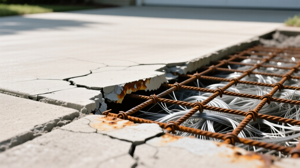
Troubleshooting Wire Mesh Reinforcement Failures
Wire mesh is unforgiving. Its effectiveness relies entirely on precise placement within the slab's cross-section. When troubleshooting mesh-reinforced slabs, look for these specific pathological signs.
1. Map Cracking and Wide Joint Spalling
If a slab exhibits wide cracks (greater than 1/8 inch) that propagate parallel to control joints, the wire mesh has likely failed to engage. This occurs when the mesh is pushed to the bottom of the slab during the concrete pour. Mesh placed in the bottom third of a slab on grade provides zero resistance to top-down drying shrinkage. The concrete shrinks, the bottom-held mesh offers no restraint, and the slab cracks deeply.
2. Rust Jacking and Delamination
In exterior slabs exposed to de-icing salts or marine environments, insufficient concrete cover over the mesh leads to chloride ingress. As the steel oxidizes, it expands up to six times its original volume. This expansion creates internal tensile forces that exceed the concrete's compressive strength, causing horizontal delamination and spalling directly above the mesh grid lines.
Troubleshooting Fiber-Reinforced Concrete (FRC) Failures
Fiber reinforcement eliminates the placement errors inherent to wire mesh, but introduces batching and mix-design vulnerabilities. Troubleshooting FRC requires investigating the ready-mix plant's procedures alongside the slab's surface conditions.
1. Fiber Balling and Surface Honeycombing
Macro-synthetic fibers (typically 1.5 to 2.25 inches in length) rely on uniform dispersion. If the fibers are added to the mixer truck before the cement and water have formed a cohesive slurry, the fibers tangle into 'balls' or 'clumps'. These clumps create localized weak zones in the matrix. On the surface, this manifests as honeycombing or concentrated clusters of plastic shrinkage cracks where the cement paste was displaced by a fiber ball.
2. Uncontrolled Structural Cracking Under Load
A common failure occurs when a specification calls for 'fiber reinforcement' but the batch plant substitutes micro-synthetic fibers (meant only for plastic shrinkage) instead of macro-synthetic or steel fibers. Micro-fibers do not provide post-cracking residual flexural strength. If a heavy-duty industrial slab cracks under forklift point-loads, verify the fiber type via a washout test. If only microscopic fibers are recovered, the slab lacks the structural capacity required by ACI Committee 544 guidelines for structural FRC.
Repair & Overlay Strategy: Which Reinforcement to Choose?
When designing a repair overlay or a full-depth patch, the choice between concrete wire mesh vs fiber depends entirely on the overlay thickness and the structural demands of the repaired zone.
Thin Overlays (1.5 to 3 Inches)
Verdict: Use Fiber Only.
Wire mesh requires a minimum of 1 inch of concrete cover on both the top and bottom to prevent corrosion and ensure bond. In a 2-inch overlay, placing wire mesh is physically impossible without violating cover requirements. For thin overlays, specify a high-performance macro-synthetic fiber at a dosage of 3.5 to 4.0 lbs per cubic yard. This provides multi-dimensional crack control without the risk of mesh protruding through the thin surface.
Full-Depth Replacements (4 Inches and Thicker)
Verdict: Macro-Fiber or Heavy-Gauge Mesh.
For 4-inch to 6-inch driveway or warehouse slabs, you have two viable paths:
- The Fiber Route: Specify ASTM C1116 Type III macro-synthetic fibers at 4.0 to 5.0 lbs/cy. This yields a residual flexural strength (RFS) of roughly 150-200 psi, sufficient for most residential and light commercial applications. It eliminates the labor cost of tying and chairing mesh.
- The Mesh Route: Use 6x6 W2.0xW2.0 (9-gauge) deformed wire mesh (ASTM A496). Deformed wires provide superior mechanical bond compared to plain wires. The mesh must be pulled to the upper third of the slab during the pour using a 'hook and pull' method, never by walking on it.
2026 Cost & Labor Breakdown for Repair Overlays
Material and labor economics heavily influence the decision between mesh and fiber in commercial repair projects. The table below reflects average 2026 pricing for a 5,000 square foot repair overlay (based on a 4-inch depth, requiring approximately 75 cubic yards of concrete).
| Cost Component | Wire Mesh Reinforcement | Macro-Synthetic Fiber Reinforcement |
|---|---|---|
| Material Cost (Reinforcement) | $1,125 ($0.225 / sq ft for W2.0 mesh + chairs) | $675 ($4.0 lbs/cy @ $2.25/lb added at plant) |
| Labor Cost (Placement & Tying) | $1,500 (approx. 20 man-hours @ $75/hr burdened) | $0 (Fiber added at batch plant, no on-site labor) |
| Total Reinforcement Cost | $2,625 ($0.525 / sq ft) | $675 ($0.135 / sq ft) |
| Risk of Placement Error | High (requires skilled ironworkers/laborers) | None (dispersed in transit mixer) |
As demonstrated, fiber reinforcement offers a massive economic advantage in repair scenarios by eliminating on-site reinforcement labor, provided the ready-mix supplier is equipped with automated fiber-dosing silos to prevent balling.
Expert FAQ on Reinforcement Repair
Can I install wire mesh over an existing cracked slab for an overlay?
No. Existing cracks will reflect through the new overlay regardless of the mesh. Before any overlay, the existing slab must be stabilized. Saw-cut and epoxy-inject existing structural cracks, and apply a bond-breaking membrane or a crack-isolation membrane (like a 1/4 inch asphaltic layer) before pouring the new fiber-reinforced overlay.
Do steel fibers outperform synthetic fibers in driveway repairs?
Steel fibers (ASTM A820) offer higher absolute tensile capacity and are excellent for heavy industrial floors. However, for exterior driveway repairs, steel fibers are generally discouraged. If the surface finishing process leaves steel fibers exposed at the top 1/8 inch of the slab, they will rust rapidly, creating unsightly orange stains and surface pitting. Synthetic fibers are chemically immune to this issue, making them the superior choice for exterior aesthetic repairs.
What is the maximum joint spacing for fiber-reinforced repair slabs?
According to industry fiber manufacturers and ACI 360 guidelines, macro-synthetic fibers do not eliminate the need for control joints; they only control random cracking between joints. For a 4-inch thick fiber-reinforced repair slab, maintain joint spacing at 10 to 12 feet in both directions (a 24:1 to 30:1 length-to-thickness ratio). Attempting to pour 'jointless' slabs using standard macro-fibers will inevitably result to uncontrolled random cracking.
Written by
James ThorntonJames Thornton is a construction industry veteran with 25 years of hands-on experience in wood framing, lumber grading, and residential building codes. He started as a framing carpenter in rural Oregon, earned his ICC Residential Building Inspector certification, and eventually became a senior plan reviewer for the City of Portland Bureau of Development Services. James holds a B.S. in Wood Science & Technology from Oregon State University and is a certified lumber grader through the West Coast Lumber Inspection Bureau (WCLIB). He has inspected over 3,000 residential construction sites and authored the city's internal guide on advanced framing techniques (2x6 at 24" O.C.). James lives in Bend, OR, where he builds custom timber-frame cabins and competes in lumberjack sports.
More from James Thornton
View all
Insulation
Best Home Insulation Materials: Complete 2026 Guide
Compare top home insulation materials for 2026. Find R-values, installed costs per square foot, and best uses for fiberglass, spray foam, and mineral wool.
Aug 4, 2026

Sustainable Building
Certify Your Green Building Material for LEED and WELL
Step-by-step guide to certifying a green building material for LEED v5 and WELL v2. Master EPDs, HPDs, and VOC limits for 2026 project specifications.
Aug 4, 2026

Stone & Masonry
Veneer Stacked Stone Panels: Interior Design & Style Showcase
Discover how veneer stacked stone panels transform interiors. Explore modern design profiles, material pairings, and technical installation specs.
Aug 4, 2026