Types of Cracks in Concrete Slabs vs. Alternative Systems
Compare common types of cracks in concrete slabs against alternative systems like post-tensioned and fiber-reinforced concrete to optimize structural integrity.

The Inevitable Reality: Types of Cracks in Concrete Slabs
Traditional cast-in-place concrete possesses high compressive strength (typically 3,000 to 5,000 PSI) but notoriously low tensile strength—roughly 10% of its compressive capacity. When tensile stresses induced by shrinkage, thermal gradients, or structural loads exceed this modulus of rupture, the matrix fails. Understanding the specific types of cracks in concrete slabs is critical for diagnosing whether a traditional slab is viable for your project or if an alternative structural system is required to mitigate failure.
Primary Crack Classifications
- Plastic Shrinkage Cracks: Occur within 1 to 4 hours of placement when the evaporation rate of surface moisture exceeds the bleed water rate. These appear as shallow, parallel fissures 0.5 mm to 2.0 mm wide, typically spaced 1 to 3 feet apart.
- Settlement Cracks: Driven by subgrade consolidation or inadequate soil compaction. These manifest as stepped or vertical displacement cracks exceeding 3 mm in width, often mirroring the underlying soil failure profile.
- Structural Overload Cracks: Result when live or dead loads exceed the slab's flexural capacity. These are typically deep, diagonal, or transverse cracks that propagate from the tension face (usually the bottom of the slab) upward.
- D-Cracking: A freeze-thaw deterioration mechanism occurring near joints and edges, characterized by a series of short, interconnected cracks caused by the expansion of freezing moisture trapped in porous aggregate.
Traditional Slabs vs. Alternative Systems: Crack-Susceptibility Matrix
To eliminate or drastically reduce the occurrence of these crack types, structural engineers increasingly specify alternative slab systems. The matrix below compares traditional reinforced concrete against three primary alternatives based on crack mitigation performance and structural behavior.
| System Type | Primary Crack Mitigation Mechanism | Reduction in Shrinkage Cracking | Typical 2026 Cost (per sq ft) |
|---|---|---|---|
| Traditional Rebar/WWM | Crack width control (does not prevent cracking) | Baseline (0%) | $5.50 - $7.50 |
| Post-Tensioned (PT) | Active compression counteracts tensile shrinkage forces | 80% - 95% | $8.50 - $12.00 |
| Macro-Synthetic FRC | 3D fiber matrix arrests micro-crack propagation early | 60% - 75% | $6.00 - $8.00 |
| Precast Hollow Core | Factory-controlled curing eliminates plastic shrinkage | 95% - 100% | $14.00 - $18.00 |
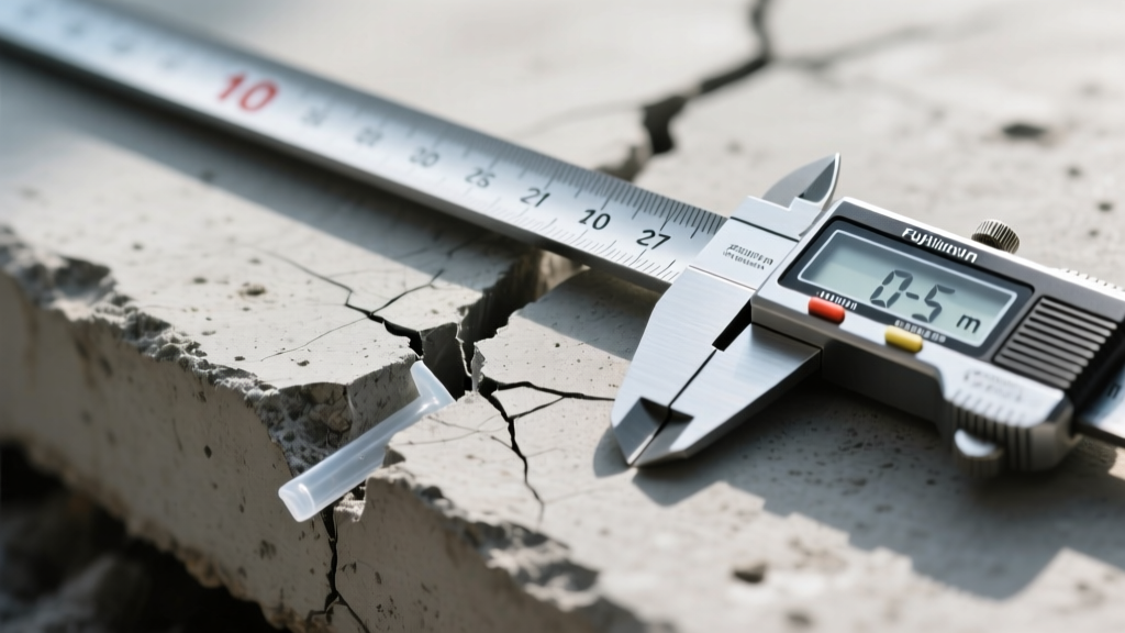
Deep Dive: Evaluating the Alternatives
1. Post-Tensioned (PT) Concrete Slabs
Post-tensioning involves threading high-strength steel tendons through plastic ducts in the slab. After the concrete reaches approximately 3,000 PSI (usually 3 to 5 days), the tendons are stressed to 25,000 PSI using hydraulic jacks and anchored. This process places the entire concrete cross-section into active compression.
Performance Impact: Because concrete is exceptionally strong in compression, the PT forces neutralize the tensile stresses that cause shrinkage and structural cracking. The Post-Tensioning Institute notes that PT slabs can span up to 40 feet without intermediate beams, significantly reducing the slab thickness required (often 5 to 7 inches compared to 8 to 12 inches for traditional reinforced slabs). This is the premier alternative for expansive clay soils where differential settlement would instantly shatter a traditional slab.
2. Macro-Synthetic Fiber-Reinforced Concrete (FRC)
Rather than relying on 2D welded wire mesh (WWM) which only controls cracks after they have already formed and widened, macro-synthetic fibers (such as Forta-Ferro or BASF MasterFiber) are batched directly into the ready-mix truck at dosages of 3 to 5 lbs per cubic yard. These fibers create a 3D internal scaffolding that intercepts micro-cracks at the microscopic level during the plastic state.
Performance Impact: FRC drastically reduces plastic shrinkage cracking by increasing the early-age tensile strain capacity of the mix. While it does not replace primary structural rebar in suspended slabs, it is highly effective for slab-on-grade industrial floors and warehouse pavements where joint spacing can be extended from the traditional 15 feet up to 50 feet or more, minimizing the number of vulnerable joints.
3. Precast Hollow Core Planks
For elevated floors and commercial roofing, precast hollow core slabs bypass the on-site curing environment entirely. Extruded in a climate-controlled factory and steam-cured, these planks experience zero plastic shrinkage or thermal gradient cracking during formation. On-site, they are grouted together, transferring loads via shear keys. The only "cracks" that may appear are minor longitudinal grout lines between planks, which are easily managed with a concrete topping slab.
Cost-to-Crack-Performance Ratio
When evaluating alternatives, the initial material cost must be weighed against the lifecycle cost of crack remediation. In 2026, professional epoxy injection for structural crack repair averages $18 to $30 per linear foot, while routing and sealing non-structural shrinkage cracks costs $4 to $8 per linear foot.
Decision Framework: Selecting Your Slab System
Use the following diagnostic flow to determine if traditional concrete is sufficient or if an alternative is mandated by site conditions:
- Assess the Subgrade: If soil testing reveals expansive clays (Plasticity Index > 25) or differential settlement risks exceeding 0.75 inches, abandon traditional slabs. Specify Post-Tensioned concrete to bridge soft spots and maintain structural integrity.
- Evaluate the Environment: If pouring in high-wind, low-humidity, or high-temperature conditions (evaporation rate > 0.2 lbs/sq ft/hour per the Federal Highway Administration guidelines), traditional slabs will almost certainly suffer plastic shrinkage. Mandate Macro-Synthetic FRC and apply a high-efficiency curing compound (ASTM C309 Type 2) immediately after finishing.
- Determine Joint Tolerance: If the end-use requires highly flat floors (FF 50 / FL 35 or higher) for narrow-aisle forklifts, traditional jointed slabs will curl and crack at the joints. Utilize FRC with joint eliminators or laser-screed post-tensioned systems.
- Analyze Span Requirements: For elevated spans exceeding 25 feet where deflection and bottom-face cracking are concerns, traditional reinforced concrete becomes excessively thick and heavy. Transition to Precast Hollow Core or PT systems to reduce dead load and eliminate tension-zone cracking.
Final Mitigation Protocols for Traditional Slabs
If budget or design constraints force the use of traditional cast-in-place concrete, strict adherence to jointing rules is non-negotiable. Control joints must be saw-cut within 4 to 12 hours of placement to a depth of exactly 25% of the slab thickness. Joint spacing (in feet) should never exceed 2 to 3 times the slab thickness (in inches). For a standard 4-inch residential slab, joints must be spaced no further than 8 to 12 feet apart. Failure to execute this precise geometry guarantees uncontrolled, random map-cracking across the surface.
Written by
David NakamuraDavid Nakamura is a licensed architect (AIA) and construction technology writer focused on sustainable building methods, mass timber engineering, and high-performance building envelopes. He holds a Master of Architecture from the University of Washington and is a certified Passive House Consultant (CPHC). David spent eight years at the Seattle firm Mithun, where he led the design of three LEED Platinum projects, before founding his own practice specializing in net-zero residential design. He serves on the editorial advisory board of GreenBuilder Magazine and has authored peer-reviewed papers on cross-laminated timber (CLT) connections for the Journal of Structural Engineering. In his spare time, David teaches woodworking at Pratt Fine Arts Center and kayaks the Puget Sound.
More from David Nakamura
View all
Construction Cost
Labor Cost to Build a Deck Per Sq Ft: 2026 Installation Guide
Discover the exact labor cost to build a deck per sq ft in 2026. This installation guide breaks down contractor rates, complexity factors, and hidden fees.
Aug 4, 2026
Construction Cost
How Much Does It Cost to Build a 3 Bedroom House? Financing Guide
Learn exactly how much it costs to build a 3 bedroom house and explore 2026 financing options, construction loan types, and budget frameworks for your build.
Aug 4, 2026
Construction Cost
Cost to Build a Tennis Court: 2026 Guide
How much does it cost to build a tennis court in 2026? Breakdowns for asphalt, concrete, and synthetic surfaces plus fencing and lighting.
Jul 30, 2026