How to Build a Deck: Navigating Span Tables and Load Ratings
Learn how to build a deck using IRC structural specifications. Master joist span tables, ledger load ratings, and footing sizing for safe, code-compliant builds.
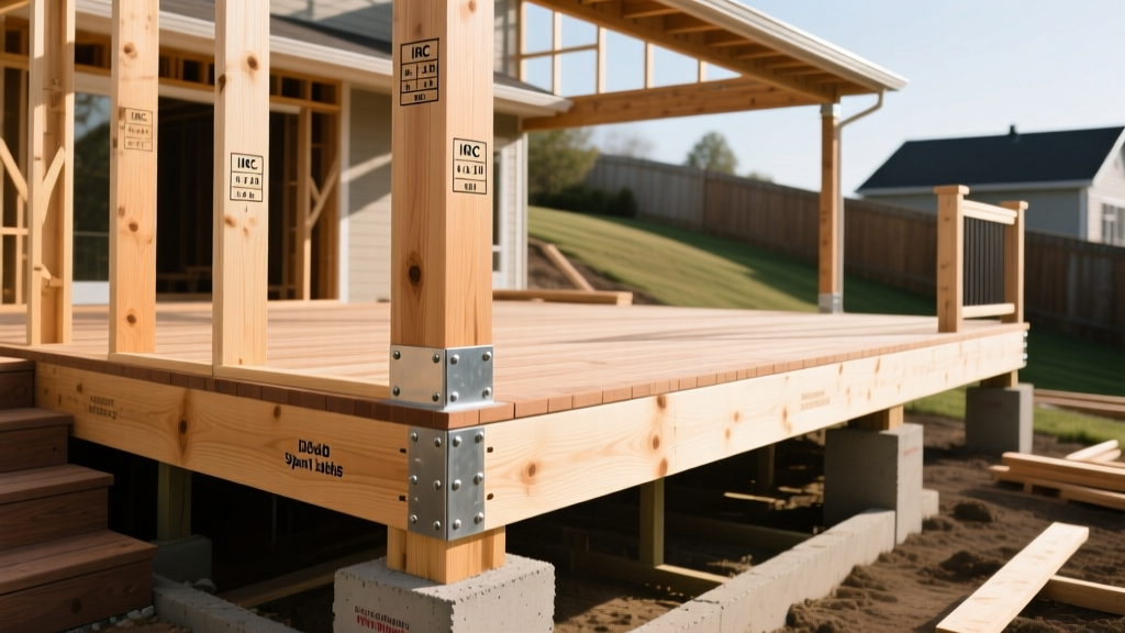
The Core Physics: Understanding Deck Load Paths and Tributary Areas
When learning how to build a deck that will pass municipal inspections and withstand decades of use, you must move beyond basic carpentry and think like a structural engineer. The International Residential Code (IRC) dictates that residential decks must support a minimum live load of 40 pounds per square foot (psf) and a dead load of 10 psf, totaling a 50 psf design load. However, understanding how this weight transfers through the structure—known as the load path—is where most DIY builders fail.
Every component of your deck must be sized based on its tributary area, which is the specific square footage of the deck surface that bears down on a single joist, beam, or footing. For example, if your joists are spaced 16 inches on center (O.C.), each joist carries the load of the decking 8 inches to its left and 8 inches to its right. Miscalculating this tributary area leads to undersized beams and catastrophic deflection under dynamic loads, such as a crowd gathering on one side of the deck during a party.
Decoding IRC Span Tables for Joists and Beams
The IRC provides prescriptive span tables that eliminate the need for complex calculus, but they require precise identification of your lumber species, grade, and spacing. The most common framing material is #2 grade Southern Pine, prized for its high bending stress (Fb) and modulus of elasticity (E) ratings. Below is a performance matrix for ground-contact rated, #2 Southern Pine joists supporting a 50 psf total load with an L/360 live load deflection limit.
| Joist Dimension | Spacing 12" O.C. | Spacing 16" O.C. | Spacing 24" O.C. |
|---|---|---|---|
| 2x6 | 9 ft. 11 in. | 9 ft. 0 in. | 7 ft. 10 in. |
| 2x8 | 13 ft. 1 in. | 11 ft. 10 in. | 10 ft. 4 in. |
| 2x10 | 16 ft. 2 in. | 14 ft. 9 in. | 12 ft. 10 in. |
| 2x12 | 18 ft. 8 in. | 17 ft. 1 in. | 15 ft. 5 in. |
Source: American Wood Council (AWC) Prescriptive Residential Wood Deck Construction Guide (DCA 6).
Beam Sizing and Cantilever Limits
Beams carry the cumulative load of the joists and transfer it to the posts. If you are building a 12-foot deep deck with joists spanning 10 feet to a central beam, that beam must support a tributary width of 10 feet. For a 10-foot tributary area, a 3-ply 2x10 #2 Southern Pine beam is rated for a maximum span of 8 feet 4 inches between posts. If your posts are spaced further apart, you must upgrade to a 3-ply 2x12 or 4-ply 2x10.
Hardware Performance: Fastener Shear and Corrosion Specs
Modern pressure-treated lumber is preserved with micronized copper azole (MCA) or alkaline copper quaternary (ACQ). While highly effective against rot, the copper in these treatments acts as a cathode, aggressively corroding standard zinc-plated or electro-galvanized hardware. To maintain structural integrity, your fasteners and joist hangers must meet specific ASTM performance ratings.
- Hot-Dipped Galvanized (HDG) G185: Meets ASTM A153 Class D. The G185 designation means the hardware has a minimum zinc coating of 1.85 ounces per square foot. This is the absolute minimum requirement for ACQ and MCA treated lumber.
- ZMAX or Z-MAX Coatings: Proprietary coatings by Simpson Strong-Tie and USP that provide a thicker zinc barrier (equivalent to G185) with a smoother finish for easier installation.
- Type 304 or 316 Stainless Steel: Required for coastal environments (within 3,000 feet of saltwater) or when using highly corrosive fire-retardant-treated (FRT) wood. Type 316 contains molybdenum, offering superior resistance to chloride pitting.
When specifying joist hangers, ensure the hanger's published allowable load exceeds the actual reaction force of the joist. For a 2x10 joist spanning 14 feet at 16" O.C., the end reaction is approximately 700 lbs. A standard Simpson LUS210Z hanger provides an allowable load of 1,435 lbs, offering a safety factor of over 2.0.
Ledger Board Attachment: The Tension and Shear Requirements
The ledger board is the most critical failure point in deck construction. According to IRC Section R507.9.1.1, the ledger must be attached to the house rim joist using 1/2-inch diameter hot-dipped galvanized lag screws or through-bolts. The spacing of these fasteners is directly tied to the joist span.
If your joists span 10 feet, 1/2-inch lag screws must be placed every 16 inches along the ledger. If the joist span increases to 14 feet, the lag screw spacing must tighten to every 11 inches. Furthermore, to prevent the deck from pulling away from the house during seismic events or heavy lateral loads, the IRC mandates lateral load connectors. Installing two Simpson Strong-Tie DTT2Z tension ties per deck, each providing a minimum 1,500 lb. tension capacity, anchors the deck joists directly to the interior floor framing of the house.
Footing Specifications Based on Soil Bearing Capacity
A perfectly framed deck will still fail if the footings sink into the ground. The IRC dictates footing diameter based on the assumed soil bearing capacity (measured in psf) and the tributary load of the posts. Most residential sites fall into the clay or sandy clay category, which carries a conservative bearing capacity of 1,500 psf to 2,000 psf.
| Soil Type | Presumptive Bearing Capacity | Min. Footing Diameter (4,000 lb load) | Min. Footing Diameter (8,000 lb load) |
|---|---|---|---|
| Clay / Sandy Clay | 1,500 psf | 22 inches | 30 inches |
| Sand / Silty Clay | 2,000 psf | 19 inches | 27 inches |
| Sandy Gravel / Gravel | 3,000 psf | 16 inches | 22 inches |
| Bedrock | 12,000 psf | 10 inches (pinned) | 12 inches (pinned) |
Expert Insight on Frost Heave: Bearing capacity is irrelevant if the footing rests in the active frost zone. Expanding ice lenses in freezing soil can exert up to 50,000 psf of uplift pressure on a concrete footing. Always excavate below your local frost line—ranging from 12 inches in the deep South to 60+ inches in northern climates—and bell the bottom of the footing to create a mechanical lock against frost jacking.
By strictly adhering to these span tables, corrosion ratings, and soil bearing matrices, you transition from guessing to engineering. This data-driven approach ensures your outdoor structure is not only code-compliant but engineered to perform flawlessly under maximum environmental and dynamic stresses.