Roof Racks for Solar & HVAC: Scenario Matching Guide
Match commercial and residential roof racks to your specific membrane, wind zone, and equipment load with this scenario-based installation guide.
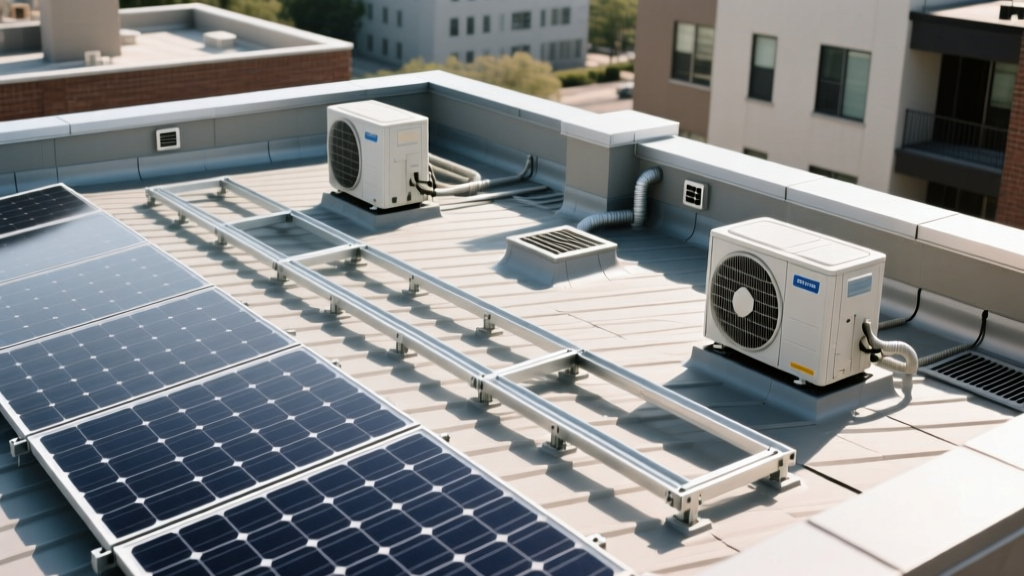
The Physics of Roof Rack Loading and Membrane Preservation
Roof racks—encompassing equipment supports for HVAC units, pipe stands, and solar mounting rails—serve as the critical structural interface between heavy dynamic loads and delicate waterproofing assemblies. Selecting the correct roof rack system is not merely a matter of weight capacity; it requires precise scenario matching based on roof slope, membrane type, regional wind uplift requirements, and seismic activity. A mismatched rack system will lead to membrane puncture, ponding water, galvanic corrosion, or catastrophic wind failure.
In 2026, building codes strictly enforce ASCE 7-22 standards for wind and seismic loads on rooftop equipment. The National Roofing Contractors Association (NRCA) explicitly warns against rigid, unisolated equipment supports that transfer vibration and thermal movement directly into the roof deck. This guide breaks down the exact roof rack configurations required for specific building scenarios, providing actionable specifications for contractors and facility managers.
Scenario 1: Non-Penetrating Ballasted Roof Racks for Flat Commercial Roofs
For flat or low-slope commercial roofs (TPO, EPDM, PVC, or Modified Bitumen), penetrating the membrane to bolt equipment racks to the deck introduces long-term leak liabilities. Non-penetrating, ballasted roof racks rely on gravity and friction to hold HVAC units, exhaust fans, and solar arrays in place.
Calculating Ballast and Footprint
Systems like the Unistrut P1000 series or Kodiak non-penetrating supports utilize a modular frame design. The fundamental rule for ballasted roof racks is maintaining a minimum of 2.0 lbs of ballast per 1 lb of equipment weight in interior roof zones, scaling up to 4.5 lbs per 1 lb in corner and perimeter zones.
- Interior Zone: Standard concrete paver ballast (typically 15-25 lbs per square foot of rack footprint).
- Perimeter Zone (10% of roof width): Requires 1.5x interior ballast.
- Corner Zone: Requires 2.0x interior ballast due to severe wind vortex uplift.
Membrane Protection Protocols
Never place bare aluminum or galvanized steel roof racks directly on a single-ply membrane. Thermal expansion of the metal will cause abrasion, while galvanic reactions can degrade certain membrane chemistries. Always install a minimum 1/4-inch thick EPDM walkway pad or a specialized high-friction slip sheet beneath every rack base plate. For TPO roofs, ensure the slip sheet is TPO-compatible to prevent plasticizer migration.
Scenario 2: Penetrating Rail Racks for Sloped Solar Arrays
When installing solar PV systems on sloped residential or commercial roofs (asphalt shingle, standing seam metal, or tile), ballasted roof racks are structurally unviable due to shear forces. Here, penetrating rail racks or mechanical seam clamps are mandatory. The Department of Energy emphasizes that structural attachment must bypass the roofing material and anchor directly into the roof rafters or trusses.
Asphalt Shingle Applications
For shingle roofs, use heavy-duty aluminum rail systems like the IronRidge XR100 or K2 Systems. The attachment hardware must feature 5/16-inch by 3.5-inch stainless steel lag bolts driven a minimum of 3 inches into the structural rafter. The critical component is the flashing: utilize integrated aluminum flashings with butyl rubber seals or EPDM gaskets. Avoid cheap plastic flashings, which become brittle under UV exposure and fail within 5 to 7 years.
Standing Seam Metal Applications
Standing seam metal roofs offer the ideal scenario for solar roof racks because they allow for entirely non-penetrating mechanical attachment. Using S-5! clamps or equivalent engineered seam grips, the rack rails bolt directly to the vertical seam. The clamp must be matched to the exact seam profile (e.g., Trapezoidal, T-Seam, or Bulb Seam) and torqued to the manufacturer's exact specification—usually between 12 and 18 ft-lbs. Over-torquing will crush the seam and compromise the roof's weathertightness.
Scenario Matrix: Matching Rack Type to Roof Assembly
| Roof Assembly | Recommended Rack System | Attachment Method | Min. Clearance | Primary Failure Risk |
|---|---|---|---|---|
| Flat TPO / PVC | Ballasted Aluminum Frame | Gravity + Friction Pads | 12 inches | Lateral sliding, membrane abrasion |
| Flat EPDM | Ballasted Steel/Aluminum | Gravity + EPDM Pads | 12 inches | Ponding water, organic debris trap |
| Sloped Asphalt Shingle | Aluminum Solar Rails | Lag Bolts + Aluminum Flashing | 4 inches (rail to roof) | Rafter splitting, flashing leaks |
| Standing Seam Metal | Rail-less or Low-Profile Rails | Mechanical Seam Clamps | 2 inches | Seam crushing, galvanic corrosion |
| Concrete Tile | Tile Replacement Mounts | Deck Anchors + Flashing | 6 inches | Tile breakage, underlayment tears |
High-Wind and Seismic Engineering Considerations
According to FEMA Building Science guidelines and modern structural codes, roof racks in High-Velocity Hurricane Zones (HVHZ) or high seismic regions require specialized engineering.
Wind Uplift (ASTM E1592)
In regions prone to hurricanes or severe straight-line winds, ballasted roof racks must undergo wind tunnel testing or rigorous structural calculation per ASTM E1592. If the calculated uplift force exceeds the dead weight of the rack and equipment, the system must transition from a purely ballasted design to a hybrid system utilizing structural adhesives or mechanical fasteners anchored into the roof deck. Alternatively, aerodynamic fairings must be added to the roof racks to reduce the drag coefficient and prevent wind from getting underneath the equipment.
Seismic Restraint
In seismic zones (e.g., California, Pacific Northwest), roof racks must accommodate lateral movement without snapping rigid pipe connections. Equipment supported by roof racks must utilize flexible conduit and piping connections. The rack itself should incorporate seismic bracing—diagonal cross-members that prevent the rack from racking or collapsing during lateral ground acceleration.
Step-by-Step Installation Protocol for Flat Roof Racks
Proper installation ensures the roof rack performs as engineered without voiding the membrane manufacturer's warranty. Follow this sequence for flat roof equipment supports:
- Site Preparation: Sweep the membrane area completely clean. Any trapped gravel or debris beneath the rack will act as a puncture point under heavy loads.
- Slip Sheet Deployment: Lay down the primary separation layer. Use a continuous sheet of 1/4-inch EPDM or a manufacturer-approved walkway pad that extends at least 6 inches beyond the rack footprint on all sides.
- Base Plate Positioning: Assemble the rack base plates on the slip sheet. Ensure the plates are perfectly level; use composite shims if the roof has a slight taper for drainage. Never use wood shims, as they will rot and compress over time.
- Frame Assembly: Erect the vertical posts and cross-members. Torque all structural bolts to the manufacturer's specifications using a calibrated torque wrench. Hand-tightening is unacceptable for dynamic load-bearing structures.
- Ballast Placement: Load the concrete pavers or steel ballast weights onto the designated base plates. Distribute the weight evenly to prevent localized point-loading on the roof deck.
- Equipment Mounting: Secure the HVAC unit or solar array to the top rails of the rack using vibration-dampening neoprene pads to prevent harmonic resonance from transferring into the building structure.
Clearance, Drainage, and Maintenance Access
A frequently overlooked aspect of roof rack specification is the clearance height. Roof racks must elevate equipment a minimum of 12 inches above the roof surface (18 inches in heavy snow climates). This clearance is non-negotiable for three reasons:
- Drainage Flow: It prevents the rack base and equipment from damming water flow toward roof drains or scuppers, which causes ponding and accelerates membrane degradation.
- Snow Accumulation: It prevents snow from burying the equipment or creating ice dams against the machinery.
- Inspection Access: It allows roofing contractors to visually inspect the membrane beneath the equipment and perform routine maintenance or re-coating without dismantling the rack.
By rigorously matching the roof rack system to the specific structural, environmental, and membrane variables of your project, you ensure a watertight, code-compliant installation that protects both the building envelope and the expensive equipment it supports.