Structural Technical Specifications for Cob Building Material
Explore the technical specifications of cob building material, including precise mix ratios, compressive strength data, and ASTM testing standards.

Core Material Composition and Sieve Analysis
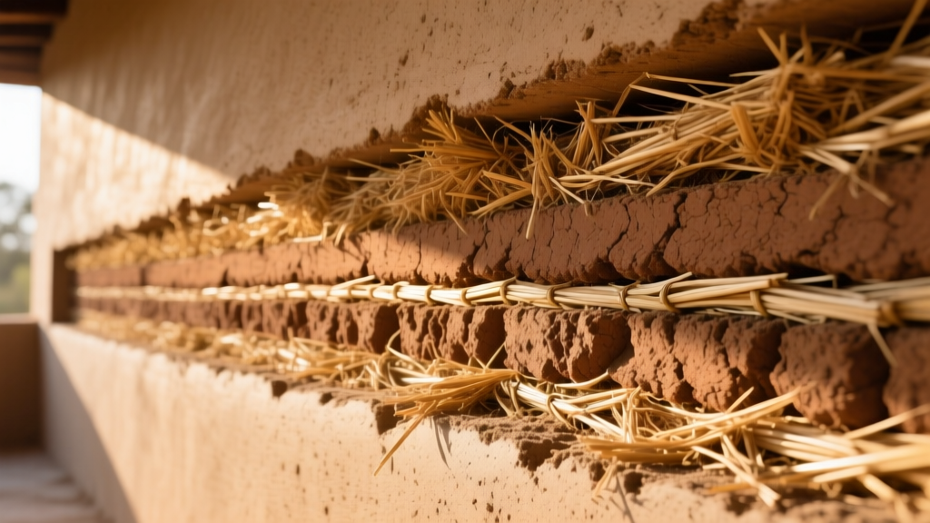
Cob building material is a monolithic, unreinforced earthen composite consisting of subsoil, water, and fibrous organic material (typically straw). Unlike rammed earth or adobe, cob is not compacted into forms or dried into bricks; it is applied wet and sculpted in place. The structural integrity of the cured wall relies entirely on the particle size distribution of the subsoil and the tensile bridging provided by the straw.
Optimal subsoil for cob must avoid high-plasticity clays like montmorillonite, which exhibit excessive volumetric shrinkage (up to 15%) upon drying. Kaolinite and illite clays are preferred due to their stable lattice structures and lower shrinkage limits. A standard sieve analysis and hydrometer test must confirm the following particle distribution for load-bearing applications:
| Particle Type | Size Range (mm) | Target Volumetric Percentage | Engineering Function |
|---|---|---|---|
| Gravel | 2.0 - 20.0 | 10% - 20% | Internal aggregate skeleton; reduces overall shrinkage. |
| Sand | 0.06 - 2.0 | 45% - 65% | Primary load-bearing matrix; provides compressive strength. |
| Silt | 0.002 - 0.06 | 10% - 20% | Filler; coats sand particles to improve clay adhesion. |
| Clay | < 0.002 | 15% - 25% | Binder; provides cohesive strength and plasticity when wet. |
Standard Mix Ratios and Proportioning
Precise proportioning is critical. While traditional cob relies on empirical field testing, modern structural engineering requires volumetric or mass-based batching. The standard volumetric ratio for a structural load-bearing cob mix is 1 part clay-rich subsoil to 2 or 3 parts sharp sand, depending on the in-situ clay content. Straw is added at a rate of 2% to 4% by volume of the dry earth mix.
Field Validation Protocols
Before scaling up to full-wall construction, batches must pass three empirical field tests to verify the technical specifications:
- The Cigar Test (Tensile Validation): Roll a wet sample into a 150mm long, 30mm diameter cylinder. Hold it horizontally by one end. The sample must support its own weight without snapping, indicating sufficient clay cohesion and straw tensile bridging.
- The Drop Test (Compressive/Sand Ratio): Form a sphere of wet cob roughly 100mm in diameter. Drop it from shoulder height (1.5m) onto a hard, flat surface. If it shatters into dust, the mix lacks clay. If it flattens into a pancake without cracking, it has too much clay. A structurally sound mix will deform slightly and exhibit minor surface cracking.
- The Linear Shrinkage Test: Pack wet cob into a 600mm long wooden trough with a 50mm square cross-section. Score a 500mm gauge line. Allow it to dry completely in the shade for 14 days. Total linear shrinkage must not exceed 3% (15mm). If it exceeds this, increase the sand aggregate ratio.
Structural and Mechanical Properties
When cured to an equilibrium moisture content (EMC) of 10-12%, cob building material exhibits specific mechanical properties that dictate its use in structural design. Engineers must account for its high mass and relatively low tensile capacity.
- Unconfined Compressive Strength (UCS): 0.5 MPa to 1.5 MPa (72 to 217 psi). High-quality, well-graded mixes with optimal compaction during the stomping/mixing phase can reach up to 2.0 MPa.
- Shear Strength: 0.15 MPa to 0.35 MPa. Highly dependent on the interlocking of the sand/gravel matrix and the cross-linking of the straw fibers.
- Modulus of Elasticity (E): 100 MPa to 500 MPa. Cob is a highly ductile, low-stiffness material, meaning it undergoes significant elastic deformation before failure.
- Dry Density: 1,500 kg/m³ to 1,800 kg/m³. This high density necessitates robust foundation engineering to prevent differential settlement.
- Slenderness Ratio Limits: For load-bearing walls, the height-to-thickness ratio must not exceed 10:1 in standard conditions, and 6:1 in high seismic risk zones. A standard structural cob wall is typically 450mm to 600mm (18 to 24 inches) thick at the base.
Thermal and Hygroscopic Performance
Cob is frequently misunderstood as an insulating material. It is, in fact, a high thermal mass material with poor thermal resistance (R-value). Its technical value lies in its ability to absorb, store, and slowly release heat, which flattens diurnal temperature swings in passive solar designs.
| Metric | Cob Building Material | Rammed Earth | Adobe Brick |
|---|---|---|---|
| Thermal Conductivity (k-value) | 0.60 - 1.00 W/mK | 1.20 - 1.50 W/mK | 0.70 - 0.90 W/mK |
| Specific Heat Capacity | ~ 1000 J/kg·K | ~ 900 J/kg·K | ~ 1050 J/kg·K |
| Vapor Permeability | High (Breathable) | Moderate | High (Breathable) |
| Typical Wall Thickness | 450 - 600 mm | 300 - 450 mm | 250 - 350 mm |
Because cob is hygroscopic, it actively buffers indoor relative humidity. The material can absorb and desorb ambient moisture without structural degradation, provided the bulk moisture content remains below 18%. Above 18% moisture, the clay binder softens, leading to a rapid loss of compressive strength and potential shear failure.
Code Compliance and ASTM Testing Standards
Integrating cob building material into modern permitted construction requires adherence to recognized earthen building codes. While the International Building Code (IBC) lacks prescriptive sections specifically for monolithic cob, engineers utilize adjacent earthen standards and specialized guides to secure permits.
The primary governing document in North America is ASTM E2392/E2392M (Standard Guide for Design of Earthen Wall Building Systems). This standard outlines the requirements for soil selection, structural design assumptions, and moisture protection. Additionally, engineers frequently reference NZS 4298:1998 (Materials and Workmanship for Earth Buildings), published by Standards New Zealand, which provides some of the most rigorous, globally recognized empirical testing methods for earth materials, including the modified cylinder compression test and the in-situ shear test.
In the UK, where cob has a continuous historical lineage, The Cob Research Centre provides vital technical data and structural testing frameworks that align with British Standards (BS EN 1995 and BS EN 1996) for masonry and timber-earth hybrid structures.
Common Failure Modes and Engineering Mitigations
Structural failures in cob are almost exclusively related to moisture ingress or inadequate geometric proportions. Understanding these failure modes is critical for specifying correct architectural details.
| Failure Symptom | Root Cause | Technical Mitigation / Specification |
|---|---|---|
| Basal erosion and wall undercutting | Capillary rise from ground moisture or rain splash-back degrading the lower clay matrix. | Specify a stem wall (stone, concrete, or fired brick) raising the cob minimum 225mm (9 inches) above finished exterior grade. Install a capillary break (e.g., HDPE membrane) between the stem wall and the cob. |
| Vertical shrinkage cracking | Excessive clay content (high montmorillonite) or rapid, uneven drying during the curing phase. | Amend subsoil with sharp sand to reduce clay fraction below 25%. Specify continuous damp-curing (misting and covering with breathable burlap) for 14-21 days post-application to control the evaporation rate. |
| Shear failure at roof plate | Concentrated point loads from roof trusses exceeding the localized compressive capacity of the cob. | Specify a continuous reinforced concrete, timber, or steel bond beam at the top of the cob wall to distribute roof loads evenly across the entire wall cross-section. |
| Deep structural fissures (diagonal) | Differential settlement of the foundation due to the extreme dead load of the cob wall. | Geotechnical soil analysis required prior to design. Specify reinforced strip foundations or engineered raft slabs designed for a minimum bearing capacity of 25 kPa (dead load) plus live loads. |
Critical Roof Overhang Specification
To protect the hygroscopic cob walls from direct precipitation, architectural plans must specify a minimum roof overhang of 450mm (18 inches) on all exposed elevations. In regions with high wind-driven rain indices, this overhang should be increased to 600mm (24 inches), or the exterior cob surface must be finished with a vapor-permeable lime-sand render (minimum 25mm thick) to act as a sacrificial weathering layer.
Written by
Sarah WhitfieldSarah Whitfield is a chartered quantity surveyor (MRICS) and construction cost analyst with 15 years of experience in material pricing, procurement strategy, and project budgeting. She earned her degree in Construction Management from the University of Reading (UK) and has worked on projects ranging from $2M custom homes to $180M mixed-use developments across North America and Europe. Sarah currently leads cost estimating for BuildMat Insight, maintaining a proprietary database of 4,000+ material price points updated quarterly. She is a frequent contributor to RSMeans cost data panels and has presented at the International Cost Engineering Council (ICEC) congress. Based in Denver, CO, Sarah is an avid trail runner and volunteer mentor for Women in Construction.
More from Sarah Whitfield
View all
Wood & Lumber
What Are the Different Types of Wood? A Builder's Guide
Compare structural softwoods, finish hardwoods, and engineered lumber. Analyze Janka ratings, MOE values, and 2026 pricing for construction.
Aug 4, 2026
Walls & Panels
Steel Framing vs Wood Framing: Corrosion and Moisture Defense
Compare steel framing vs wood framing for moisture resistance. Learn about galvanized coatings, condensation risks, and corrosion protection strategies.
Jul 21, 2026

Stone & Masonry
How to Cut Stone Veneer: Wet Saw vs Grinder Comparison
Compare the best tools for cutting stone veneer. We review wet saws, angle grinders, and chop saws to help you achieve clean, chip-free cuts.
Jul 21, 2026