Electric Insulation Materials: Matching Dielectric Scenarios
Match electric insulation materials to specific scenarios. Compare dielectric strength, thermal ratings, and failure modes for PTFE, XLPE, and mica.
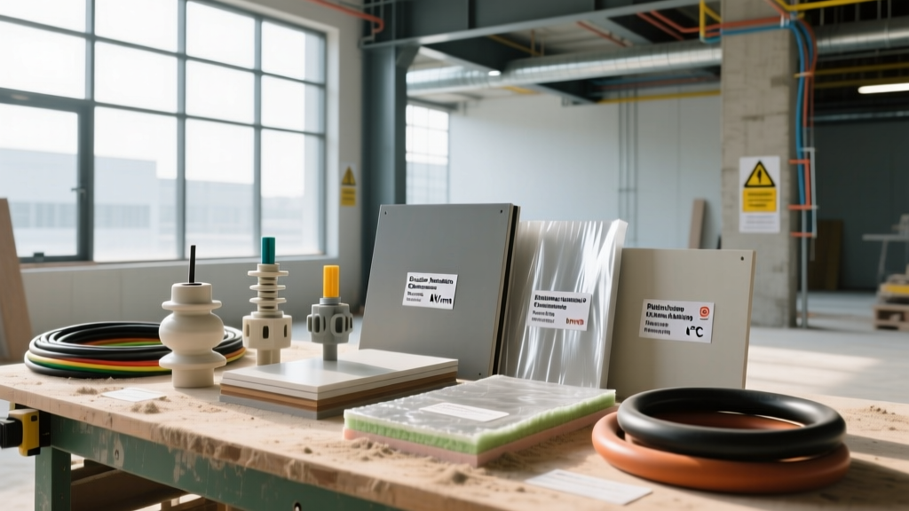
The Engineering Reality of Dielectric Selection
Selecting electric insulation is rarely a one-size-fits-all decision. The catastrophic failure of an electrical system rarely stems from the conductor itself; it almost always originates from the degradation, misapplication, or dielectric breakdown of the insulating material. When matching insulation to an application, engineers must balance three competing physical properties: dielectric strength (resistance to electrical puncture), thermal endurance (resistance to chemical breakdown under heat), and environmental tracking (resistance to surface carbonization). A material that excels in high-voltage underground transmission may fail rapidly in a high-temperature industrial motor due to thermal aging.
This guide provides a scenario-driven framework for selecting electric insulation materials, detailing exact material specifications, failure modes, and 2026 procurement baselines for industrial and commercial applications.
Core Dielectric and Thermal Parameters
Before matching materials to scenarios, it is critical to standardize the metrics used for evaluation. Relying solely on voltage ratings without considering thermal class or tracking resistance leads to premature system failure.
- Dielectric Strength (kV/mm): The maximum electric field a material can withstand before it becomes conductive. Measured in kilovolts per millimeter of thickness. Note that dielectric strength decreases non-linearly as material thickness increases.
- Thermal Class (IEC 60085): Defines the maximum continuous operating temperature before the material loses 50% of its mechanical or dielectric properties. Ranges from Class Y (90°C) to Class C (above 180°C, often up to 250°C+ for inorganic materials).
- Comparative Tracking Index (CTI): Measured in volts, this indicates the material's resistance to surface tracking (the formation of conductive carbon paths due to moisture and electrical arcing). A CTI above 600V is required for harsh, humid environments.
Application-Fit Matrix: Material Selection
The following matrix cross-references common electric insulation materials with their physical limits and ideal application scenarios.
| Material | Dielectric Strength | Max Temp (Class) | CTI Rating | Optimal Scenario |
|---|---|---|---|---|
| XLPE (Cross-linked PE) | 20 - 30 kV/mm | 90°C (Class A) | N/A (Encapsulated) | Medium/High-voltage underground distribution cables |
| PTFE (Polytetrafluoroethylene) | 60 - 100 kV/mm | 260°C (Class C) | >600V | Aerospace wiring, high-frequency data cables, chemical plants |
| Silicone Rubber | 15 - 25 kV/mm | 200°C (Class H/C) | >600V | Outdoor high-voltage terminations, flexible heating elements |
| Mica (Phlogopite/Muscovite) | 40 - 100 kV/mm | 1000°C (Inorganic) | N/A | Induction furnaces, high-temp motor slot liners, fire-resistant cables |
| Epoxy Resin (Cast) | 15 - 20 kV/mm | 130°C - 155°C (B/F) | 175V - 250V | Switchgear busbar encapsulation, instrument transformers |
Scenario-Specific Selection Guides
Scenario A: Medium-Voltage Underground Distribution (15kV - 35kV)
For underground utility grids, Cross-Linked Polyethylene (XLPE) is the undisputed standard. However, standard XLPE is highly susceptible to "water treeing"—microscopic dendritic channels that form in the presence of moisture and alternating electric fields, eventually leading to electrical treeing and catastrophic breakdown. For 2026 grid modernization projects, specify TR-XLPE (Tree-Retardant XLPE). TR-XLPE incorporates voltage stabilizers and moisture inhibitors that extend cable life from 20 years to over 40 years in wet duct environments. According to research from the Electric Power Research Institute (EPRI), utilizing TR-XLPE with a co-extruded semiconducting shield reduces partial discharge inception by up to 40% compared to standard thermoplastic alternatives.
Scenario B: High-Temperature Industrial Motors and Generators
In large industrial motors (e.g., 4160V induction motors), the stator windings experience immense thermal and mechanical stress. Standard polymer films will melt or degrade. The correct application-fit is Mica-based composites. Specifically, use Phlogopite mica tape bonded with a silicone or epoxy resin for Class H (180°C) or Class C (220°C) applications. Phlogopite mica maintains its dielectric integrity up to 1000°C, providing critical fire-survival time. For the slot liners, use a composite of Nomex 410 (aramid paper) laminated with mica to provide both the necessary mechanical stiffness for insertion and the dielectric strength to prevent phase-to-ground faults.
Scenario C: Outdoor High-Voltage Terminations and Insulators
Outdoor environments introduce UV radiation, acid rain, and salt fog, which cause surface tracking on traditional ceramic or epoxy insulators. High-Temperature Vulcanizing (HTV) Silicone Rubber is the required material here. Silicone rubber possesses unique hydrophobic recovery properties; even after surface arcing degrades the top molecular layer, low-molecular-weight silicone chains migrate to the surface, restoring water repellency and preventing the formation of continuous conductive water films. Specify silicone formulations loaded with 40-50% alumina trihydrate (ATH) filler, which releases water vapor when heated by dry-band arcing, effectively quenching the electrical tracking process.
Unlike liquid or gas insulation, solid electric insulation (like cast epoxy or thick PTFE) cannot self-heal. Microscopic voids trapped during manufacturing will ionize under high voltage, causing partial discharge (PD). This localized erosion creates carbonized channels that inevitably lead to total dielectric puncture. Always specify vacuum-cast epoxy (VPI - Vacuum Pressure Impregnation) for switchgear components to ensure void-free solidification.
Troubleshooting Insulation Failure Modes
When an electrical system experiences insulation failure, identifying the root cause dictates the corrective material selection. Use this diagnostic framework:
- Symptom: Surface carbonization and arcing in humid environments.
Root Cause: Low Comparative Tracking Index (CTI).
Corrective Action: Replace standard phenolic or low-grade epoxy components with high-CTI materials like PTFE, Silicone Rubber, or specialized tracking-resistant epoxy formulations (CTI > 600V). - Symptom: Insulation becomes brittle and cracks upon mechanical flexing.
Root Cause: Thermal aging exceeding the material's thermal class, causing plasticizer migration or polymer chain scission.
Corrective Action: Upgrade the thermal class. If currently using PVC (Class A, 105°C) or standard PE, transition to XLPE (90°C continuous, but highly cross-linked) or PTFE (260°C) depending on the flexibility requirements. - Symptom: Unexplained breakdown in underground cables after 5-10 years.
Root Cause: Water treeing transitioning to electrical treeing.
Corrective Action: Mandate TR-XLPE (Tree-Retardant) insulation with a bonded metallic moisture barrier (e.g., corrugated aluminum sheath) for the replacement run.
Procurement and Cost Baselines (2026)
Material costs for electric insulation vary wildly based on chemical complexity and manufacturing tolerances. When budgeting for industrial projects, use the following baseline metrics for raw insulation compounds and fabricated forms:
- XLPE Cable Insulation Compound: $2.50 - $4.00 per kg. (TR-XLPE variants command a 15-20% premium over standard XLPE).
- PTFE Film and Tubing: $45.00 - $85.00 per kg. The high cost is justified in aerospace and chemical processing where no other polymer can survive the combined thermal and chemical attack.
- Mica Boards and Tapes: $15.00 - $35.00 per kg. Calcined mica boards (used in induction furnaces) are at the higher end of this spectrum due to the high-temperature silicone binders required.
- Cast Epoxy Resin Systems (Bisphenol-A + Anhydride Hardeners): $8.00 - $14.00 per kg. Costs scale significantly when nano-fillers (like silica or alumina) are added to improve thermal conductivity and reduce the coefficient of thermal expansion (CTE).
Understanding the fundamental physics of dielectric breakdown and thermal degradation allows engineers to move beyond generic specifications. By matching the exact environmental and electrical stresses of a scenario to the molecular properties of the insulation material, system reliability is drastically improved, and lifecycle maintenance costs are minimized. For further reading on advanced material behaviors in electrical grids, refer to the U.S. Department of Energy's materials science guidelines, which detail the ongoing evolution of polymeric and inorganic insulators in modern infrastructure.