Troubleshooting Noise Reducing Gypsum Board Acoustic Failures
Fix acoustic leaks in your noise reducing gypsum board. Expert troubleshooting for flanking noise, outlet breaches, and damping compound failures.

The Anatomy of an Acoustic Failure
Installing premium acoustic drywall does not guarantee a quiet room. When a wall assembly fails to meet its laboratory-tested Sound Transmission Class (STC) rating, the culprit is rarely the board itself. According to the Gypsum Association, a 1% gap or unsealed penetration in a partition can reduce the overall STC rating of a wall by up to 50%. Noise reducing gypsum board relies on mass, decoupling, and damping to block sound waves; when any of these mechanisms are compromised by poor installation or structural flanking, high-performance assemblies degrade to the level of standard drywall.
Troubleshooting these failures requires a systematic approach to identify whether the issue stems from airborne leaks, impact flanking, or constrained-layer damping (CLD) delamination. This guide provides field-tested diagnostic protocols and exact repair procedures for compromised soundboard installations.
Symptom 1: High-Frequency Voice Transmission (Airborne Leaks)
If you can clearly hear conversations, television dialogue, or high-pitched noises through a wall rated for STC 50 or higher, you have an airborne acoustic leak. High-frequency sound waves act like water; they will exploit the smallest pinhole or unsealed joint.
The Electrical Box Breach
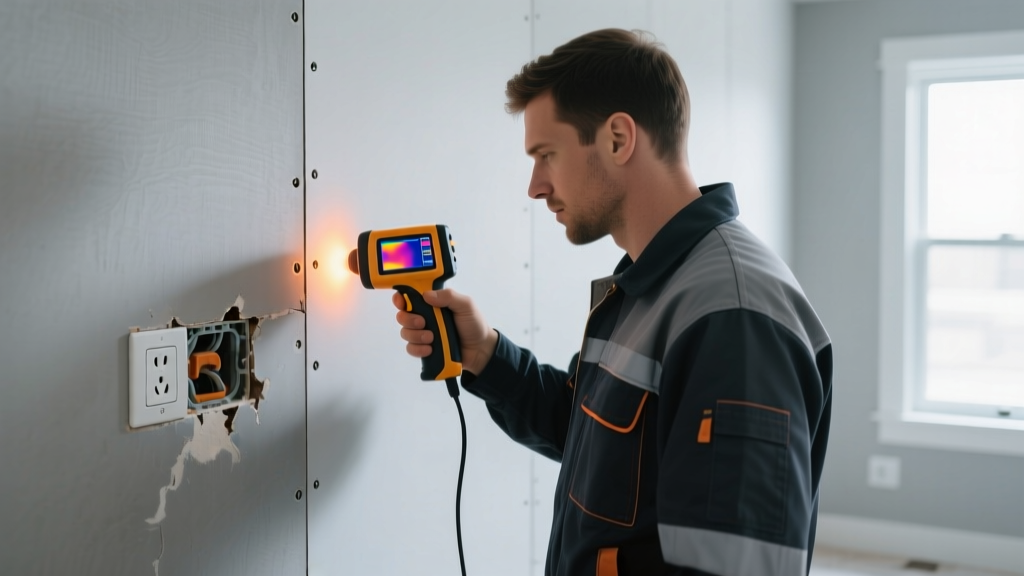
The most common failure point in noise reducing gypsum board is the electrical outlet cutout. Standard drywall cutouts leave a 1/8-inch to 1/4-inch gap around the plastic or metal junction box. Furthermore, installing electrical boxes back-to-back on opposite sides of a stud bay completely destroys the mass barrier, creating a direct acoustic tunnel.
The Repair Protocol:
- Remove the outlet cover and receptacle.
- Wrap the exterior of the electrical box with an STI Putty Pad (model STI-PP-100) or equivalent intumescent acoustic putty pad. The pad must extend at least 2 inches beyond the box edges on all sides.
- Inject ASTM E90 compliant acoustic sealant, such as OSI SC-175 or Tremco Acoustical Sealant, into the gap between the gypsum board cutout and the putty pad.
- Reinstall the receptacle, ensuring the device ears compress tightly against the drywall face.
Perimeter and Track Leaks
Soundboard must never hard-touch the floor, ceiling, or adjacent walls. If the bottom edge of the drywall rests directly on a concrete slab or hardwood floor, impact vibrations will transfer directly into the board. Conversely, if a 1/2-inch gap was left at the floor but filled with standard paintable latex caulk instead of acoustic sealant, the sealant will crack and fail under structural deflection, opening an airborne leak.
The Fix: Dig out hardened standard caulk from the bottom track using a hook-blade utility knife. Vacuum the debris, and inject a continuous 3/8-inch bead of non-hardening acoustical sound sealant. Tool it smooth with a putty knife dipped in soapy water.
Symptom 2: Low-Frequency Rumble and Impact Noise (Flanking)
If the wall blocks voices but transmits bass from a subwoofer, footsteps from upstairs, or the thud of a closing door, you are dealing with structure-borne impact noise and flanking paths. Noise reducing gypsum board is highly effective at blocking airborne sound, but low-frequency impact noise bypasses the wall entirely by traveling through the building's structural framing.
Diagnosing Flanking Paths
Flanking occurs when continuous rigid materials bridge the acoustic isolation. Common culprits include:
- Hardwood or tile flooring running continuously under the partition wall.
- Rigid HVAC ductwork penetrating the wall cavity without flexible canvas connectors.
- Plumbing pipes rigidly strapped to the same studs holding the soundboard.
The Repair Protocol: You cannot easily fix structural flanking without demolition, but you can mitigate it. Install a resilient baseboard shoe molding. Apply a 1/4-inch bead of acoustic sealant to the back of a thick MDF or rubber baseboard, and mount it to the wall (not the floor) using construction adhesive, leaving a 1/8-inch gap between the bottom of the baseboard and the floor. Fill that bottom gap with a color-matched acoustic sealant to decouple the floor from the wall assembly.
Symptom 3: Delamination and Damping Compound Failure
Advanced noise reducing gypsum board, such as PABCO Gypsum QuietRock 545 or CertainTeed SilentFX QuickCut, utilizes Constrained Layer Damping (CLD). These boards feature a viscoelastic polymer core sandwiched between two layers of gypsum. When sound waves hit the board, the core shears, converting acoustic energy into negligible heat.
The Fastening Failure
CLD boards require specific fastening schedules to function. If the board is under-screwed, the polymer core cannot compress and shear properly against the framing, resulting in a 'hollow' acoustic response and drastically reduced STC performance. Conversely, over-driving screws (breaking the paper face) eliminates the clamping force entirely.
Required Screw Schedule for 5/8-inch CLD Soundboard:
- Walls: 1-1/4 inch Type S bugle-head screws, spaced 16 inches on center (O.C.) at the studs.
- Ceilings: 1-1/4 inch Type S screws, spaced 12 inches O.C. at the joists/channels.
- Perimeter: Screws must be placed 3/8 inch from the edges and spaced 8 inches O.C.
If a wall sounds hollow when tapped and fails to block mid-frequency noise, the board was likely under-fastened or the screws popped due to framing shrinkage. The repair requires adding supplemental fasteners and applying Green Glue Noiseproofing Compound behind the screw heads before mudding.
Acoustic Troubleshooting Decision Matrix
Use this field matrix to rapidly diagnose the root cause of your soundboard failure and apply the correct intervention.
| Symptom | STC Impact | Root Cause | Field Verification | Repair Action |
|---|---|---|---|---|
| Clear voice transmission | -15 to -25 STC | Unsealed electrical boxes or perimeter gaps | Shine a high-lumen flashlight inside a dark adjacent room; look for light leaks around outlets and tracks. | Apply STI putty pads and inject OSI SC-175 acoustic sealant into all perimeter joints. |
| Bass rumble / Subwoofer bleed | -5 to -10 STC | Structural flanking via continuous flooring or rigid HVAC | Use a mechanic's stethoscope on floor tracks and ceiling joints during bass playback. | Decouple baseboards; install flexible canvas duct connectors; add mass loaded vinyl (MLV) to floor. |
| Hollow wall sound / Mid-frequency bleed | -10 to -20 STC | CLD core delamination or improper screw schedule | Tap wall with knuckles; listen for hollow resonance. Check for popped screw heads. | Add supplemental 1-1/4' Type S screws at 12' O.C.; inject Green Glue behind popped heads. |
| Rattling fixtures / Buzzing | -2 to -5 STC | Loose HVAC registers or recessed lighting cans touching drywall | Remove register covers and inspect for direct metal-to-gypsum contact. | Apply neoprene gasket tape between the drywall face and all fixture flanges. |
Step-by-Step Repair Protocol for Compromised Soundboard
When a section of noise reducing gypsum board is physically damaged (e.g., from plumbing access or impact), standard drywall patching techniques will create a severe acoustic weak point. Follow this strict protocol to maintain the assembly's STC rating.
- Cut a Clean Perimeter: Use a drywall router or keyhole saw to cut out the damaged section. Ensure the cut edges fall exactly on the center of the wall studs to provide a solid nailing surface.
- Install Backing Strips: Cut 1/2-inch plywood strips 2 inches wider than the hole. Apply acoustic sealant to the back of the existing drywall edges, insert the plywood strips, and secure them with 1-1/4 inch screws.
- Prep the Patch: Cut a replacement piece of the exact same noise reducing gypsum board model. Do not substitute standard drywall for a patch; the mass differential will cause sound to funnel through the lighter patch.
- Seal and Secure: Apply a continuous bead of acoustic sealant to the plywood backing strips. Press the patch into place and secure with Type S screws every 6 inches along the perimeter.
- Fill and Finish: Fill the 1/8-inch perimeter gap with acoustic sealant. Allow it to cure for 24 hours. Once cured, apply a setting-type joint compound (like Durabond 45) for the first coat to bridge the gap rigidly, followed by standard finishing mud and tape for the final coats.
2026 Material Costs and Product Specifications
Budgeting for acoustic repairs requires accurate pricing for specialized materials. Standard drywall mud and tape are insufficient for sound-rated assemblies. Below are the current market averages for premium acoustic repair materials:
- Noise Reducing Gypsum Board (5/8-inch Type X): QuietRock 545 averages $75 to $85 per 4x8 sheet. CertainTeed SilentFX QuickCut ranges from $60 to $70 per sheet.
- Viscoelastic Damping Compound: Green Glue Noiseproofing Compound (Case of 12 tubes) costs approximately $180 to $210. Each tube covers roughly 16 square feet when applied between two rigid layers.
- Acoustical Sound Sealant: OSI SC-175 or Tremco Acoustical Sealant costs $8 to $12 per 28-ounce cartridge. A standard 10-foot wall-to-floor joint requires roughly one cartridge.
- Intumescent Putty Pads: STI Putty Pads (STI-PP-100) cost $4 to $6 per pad. Required for every electrical box penetration in a fire- and sound-rated assembly.
Preventative Maintenance for Acoustic Assemblies
Acoustic partitions are dynamic; they shift with seasonal humidity, structural settling, and HVAC vibrations. To maintain the integrity of your noise reducing gypsum board, conduct an annual visual inspection of all perimeter joints and electrical penetrations. Look for hairline cracks in the paint at the ceiling-to-wall junction and around outlet covers. If cracks appear, do not simply paint over them. Score the crack, inject a minimal amount of paintable, non-hardening acoustic sealant, and re-tape the joint using fiberglass mesh tape and setting-type compound. Proactive maintenance ensures your investment in premium soundboard continues to deliver laboratory-grade acoustic isolation for the lifespan of the building.
Written by
David NakamuraDavid Nakamura is a licensed architect (AIA) and construction technology writer focused on sustainable building methods, mass timber engineering, and high-performance building envelopes. He holds a Master of Architecture from the University of Washington and is a certified Passive House Consultant (CPHC). David spent eight years at the Seattle firm Mithun, where he led the design of three LEED Platinum projects, before founding his own practice specializing in net-zero residential design. He serves on the editorial advisory board of GreenBuilder Magazine and has authored peer-reviewed papers on cross-laminated timber (CLT) connections for the Journal of Structural Engineering. In his spare time, David teaches woodworking at Pratt Fine Arts Center and kayaks the Puget Sound.
More from David Nakamura
View all
Construction Cost
Labor Cost to Build a Deck Per Sq Ft: 2026 Installation Guide
Discover the exact labor cost to build a deck per sq ft in 2026. This installation guide breaks down contractor rates, complexity factors, and hidden fees.
Aug 4, 2026

Construction Cost
How Much Does It Cost to Build a 3 Bedroom House? Financing Guide
Learn exactly how much it costs to build a 3 bedroom house and explore 2026 financing options, construction loan types, and budget frameworks for your build.
Aug 4, 2026
Construction Cost
Cost to Build a Tennis Court: 2026 Guide
How much does it cost to build a tennis court in 2026? Breakdowns for asphalt, concrete, and synthetic surfaces plus fencing and lighting.
Jul 30, 2026