Cold-Formed Steel Framing: A Selection Framework for Builders
Master cold-formed steel framing selection with this framework. Compare gauges, yield strengths, coatings, and costs for structural and non-structural builds.
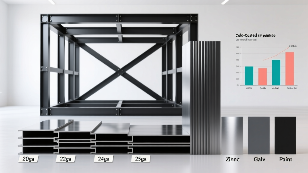
The Core Decision Matrix: Structural vs. Non-Structural CFS
Selecting the correct cold-formed steel (CFS) framing begins with a binary classification: is the member load-bearing (structural) or merely serving as a partition (non-structural)? Misclassifying these members leads to either catastrophic deflection or severe budget overruns. The American Iron and Steel Institute (AISI) governs these classifications under distinct standards. Structural framing follows AISI S200 and S240, requiring rigorous engineering for axial, shear, and moment capacities. Non-structural framing falls under AISI S220, designed strictly to support the weight of the assembly and resist minimal lateral loads.
| Feature | Structural CFS (Load-Bearing) | Non-Structural CFS (Partitions) |
|---|---|---|
| Governing Standard | AISI S200 / S240 | AISI S220 |
| Minimum Flange Width | 1-3/8 inches (typically 1-5/8" to 2") | 1-1/4 inches (typically 1-1/4" to 1-5/8") |
| Web Punchouts | Engineered specifically; often omitted in high-shear zones | Standardized knockouts for MEP routing |
| Typical Applications | Exterior load-bearing walls, floor joists, roof trusses | Interior demising walls, furring, soffits, shaft walls |
| Lip Requirement | Minimum 1/2" return lip required for compression elements | Lips often omitted (e.g., standard C-studs) or minimal |

Decoding Gauge, Mil Thickness, and Yield Strength
The construction industry historically relies on 'gauge' numbers, but this nomenclature is imprecise and inversely proportional to thickness. For accurate specification and procurement, always default to mil thickness (1 mil = 0.001 inches) and minimum yield strength. According to the Cold-Formed Steel Engineers Institute (CFSEI), modern structural design software requires exact decimal thicknesses to calculate section moduli and moments of inertia accurately.
The Standard Thickness Progression
- 33 mil (20 gauge): The baseline for light structural load-bearing walls and heavy-duty non-structural partitions. Minimum thickness: 0.0329".
- 43 mil (18 gauge): Used for mid-rise exterior load-bearing walls and floor joists up to 12-foot spans. Minimum thickness: 0.0428".
- 54 mil (16 gauge): Required for high-load transfer walls, shear walls, and longer span joists. Minimum thickness: 0.0538".
- 68 mil (14 gauge): Reserved for heavy axial loads, podium construction, and transfer trusses. Minimum thickness: 0.0677".
- 97 mil (12 gauge) & 118 mil (10 gauge): Specialized heavy structural applications, often used in built-up columns or heavy header tracks.
The 33 ksi vs. 50 ksi Yield Strength Threshold
Yield strength (Fy) dictates how much stress the steel can endure before permanent deformation.
Grade 33 (33 ksi): Standard for 33 mil (20ga) and 27 mil (22ga) members. Highly ductile, making it easier to cut and screw on-site without work-hardening the metal and snapping fastener heads.
Grade 50 (50 ksi): Standard for 43 mil (18ga) and thicker members. Provides roughly 50% more load capacity for the same cross-section. However, Grade 50 requires specialized self-drilling screws with hardened points to penetrate the denser steel without 'walking' or burning out the drill motor.
Galvanization and Coating Selection for Corrosion Resistance
Cold-formed steel is coated with zinc via the hot-dip process to prevent oxidation. The coating designation (e.g., G60, G90) refers to the total weight of zinc on both sides of the sheet per square foot. Specifying the wrong coating is a primary cause of premature framing failure in high-humidity environments.
G60 (0.60 oz/sq ft): The industry standard for interior, climate-controlled partitions and structural walls enclosed behind vapor barriers. Do not use in contact with concrete or masonry.
G90 (0.90 oz/sq ft): Mandatory for exterior load-bearing walls, parapets, and any framing exposed to weather during construction delays. Also required for bottom tracks bolted directly to concrete slabs to resist alkaline corrosion.
Galvanealed: Zinc-iron alloy coating. Excellent for paint adhesion but offers inferior bare corrosion resistance compared to pure zinc. Use only if the framing will be immediately encapsulated and painted.
Cost Benchmarking: 2026 CFS Material Estimates
Material costs for CFS fluctuate with global zinc and hot-rolled coil prices. As of early 2026, CFS remains highly competitive against dimensional lumber, particularly for commercial and multi-family projects where fire ratings and acoustic performance are mandated. The pricing below reflects national averages for raw material (stud and track) before labor, taxes, or freight surcharges.
| Member Type | Thickness / Grade | Coating | Est. Cost per Linear Foot (2026) |
|---|---|---|---|
| Non-Structural Stud (Partition) | 25 mil / 33 ksi | G40 | $0.85 - $1.10 |
| Structural Stud (Light Load) | 33 mil (20ga) / 33 ksi | G60 | $1.95 - $2.45 |
| Structural Stud (Mid-Rise) | 43 mil (18ga) / 50 ksi | G60 | $2.80 - $3.50 |
| Structural Stud (Heavy Load) | 54 mil (16ga) / 50 ksi | G60 | $4.10 - $5.20 |
| Exterior Load-Bearing Stud | 43 mil (18ga) / 50 ksi | G90 | $3.40 - $4.15 |
| Structural Track (Top/Bottom) | 54 mil (16ga) / 50 ksi | G90 | $4.50 - $5.80 |
Step-by-Step Selection Workflow for Mid-Rise Projects
When specifying CFS for a 3-to-5 story wood-framed or hybrid building with steel interior cores, follow this sequential framework to optimize both structural integrity and thermal performance.
- Define the Load Path and Axial Demands: Calculate the dead and live loads transferring from the roof and upper floors. Use the manufacturer's load-span tables to select the minimum mil thickness and yield strength that satisfies the axial load without exceeding the allowable deflection (typically L/240 for walls supporting brittle finishes like stucco or tile).
- Mitigate Thermal Bridging in Exterior Walls: Standard solid-web CFS studs act as thermal shorts, transferring heat directly through the wall cavity. For exterior assemblies, specify slotted-web studs (e.g., thermal studs with staggered cutouts in the web). This increases the thermal resistance (R-value) of the steel itself by up to 40%, preventing interior condensation and reducing HVAC loads.
- Specify Web Crippling Reinforcements: Thin webs (33 mil and 43 mil) are highly susceptible to 'web crippling'—a localized buckling failure where concentrated loads (like floor joists or heavy headers) bear directly on the top track. Always specify bearing stiffeners, clip angles, or doubled studs at point-load locations to transfer the shear force safely into the web.
- Match Fasteners to Steel Grade: Do not use standard drywall screws for structural connections. Specify self-drilling Tek screws. For 33 mil (Grade 33) steel, #8 x 1-5/8" hex-washer head screws are standard. For 54 mil and thicker (Grade 50) steel, step up to #10 or #12 screws with a #3 drill point to ensure clean penetration without stripping the threads.
Common Specification Mistakes and Edge Cases
1. Ignoring Lateral-Torsional Buckling in Joists
When using CFS joists for floor systems, the compression flange is prone to lateral-torsional buckling if left unbraced. Relying solely on the subfloor sheathing for bracing is a critical error if the sheathing is not installed immediately. You must specify continuous lateral bracing (CLB) or periodic strap bracing bridging the bottom flanges at intervals not exceeding 12 feet, per AISI S210.
2. Overlooking Track-to-Concrete Alkaline Reactions
When anchoring bottom tracks directly to a cured concrete slab, the high alkalinity of the concrete (pH 12-13) will rapidly degrade standard G60 zinc coatings, leading to base-metal corrosion. Always specify G90 coated tracks for slab contact, and apply a continuous bead of polyurethane sealant or a specialized sill sealer membrane between the track and the concrete to create a physical moisture and chemical barrier.
3. Deflection Head Clips vs. Slip Tracks
In multi-story construction, floor slabs deflect under live loads. If interior non-load-bearing partition walls are framed tight to the slab above, slab deflection will crush the top track, bowing the studs and cracking the drywall. To resolve this, specify deflection clips (which allow the stud to slide vertically within the track) or deep-leg slip tracks (where the stud extends into a deep top track with a 1-inch gap left at the top). Never rigidly screw the top flange of a partition stud to the structure above without accommodating this vertical movement.
Written by
James ThorntonJames Thornton is a construction industry veteran with 25 years of hands-on experience in wood framing, lumber grading, and residential building codes. He started as a framing carpenter in rural Oregon, earned his ICC Residential Building Inspector certification, and eventually became a senior plan reviewer for the City of Portland Bureau of Development Services. James holds a B.S. in Wood Science & Technology from Oregon State University and is a certified lumber grader through the West Coast Lumber Inspection Bureau (WCLIB). He has inspected over 3,000 residential construction sites and authored the city's internal guide on advanced framing techniques (2x6 at 24" O.C.). James lives in Bend, OR, where he builds custom timber-frame cabins and competes in lumberjack sports.
More from James Thornton
View all
Insulation
Best Home Insulation Materials: Complete 2026 Guide
Compare top home insulation materials for 2026. Find R-values, installed costs per square foot, and best uses for fiberglass, spray foam, and mineral wool.
Aug 4, 2026

Sustainable Building
Certify Your Green Building Material for LEED and WELL
Step-by-step guide to certifying a green building material for LEED v5 and WELL v2. Master EPDs, HPDs, and VOC limits for 2026 project specifications.
Aug 4, 2026
Stone & Masonry
Veneer Stacked Stone Panels: Interior Design & Style Showcase
Discover how veneer stacked stone panels transform interiors. Explore modern design profiles, material pairings, and technical installation specs.
Aug 4, 2026