Optimizing Steel Grades in Light Steel Framing Design Software
Learn how light steel framing design software optimizes 33 ksi and 50 ksi steel grades for structural efficiency, cost savings, and CNC output.
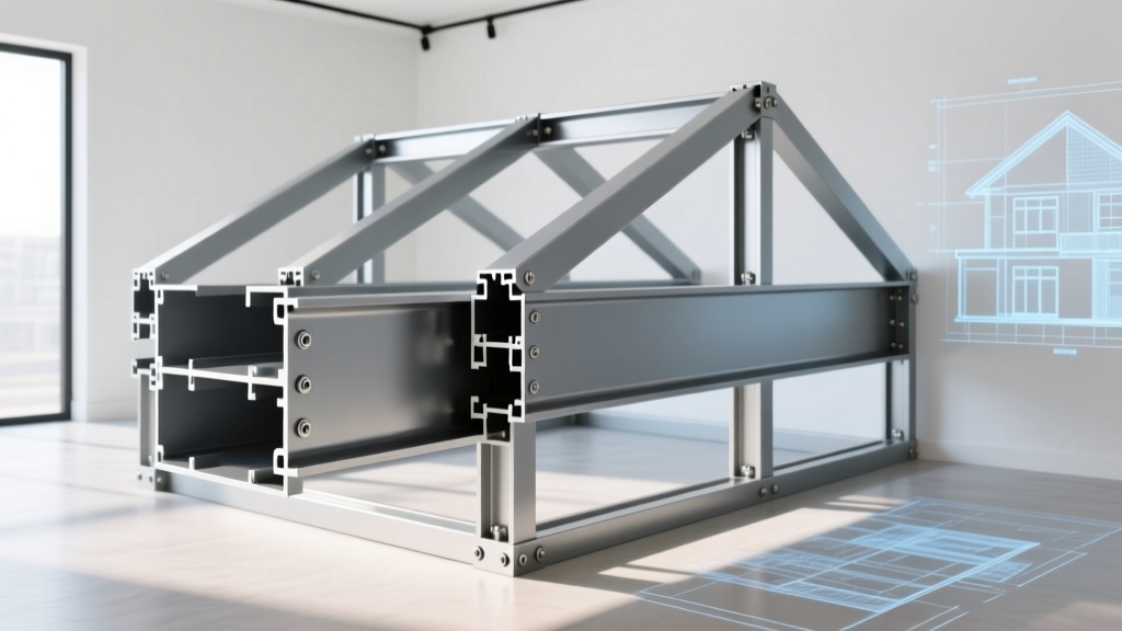
The Intersection of Metallurgy and Digital Twin Modeling
Modern cold-formed steel (CFS) construction relies heavily on the precision of light steel framing design software to translate architectural intent into manufacturable, structurally sound components. However, the structural integrity of a light gauge steel framing (LGSF) project is not solely determined by the geometry of the studs and tracks; it is fundamentally governed by the metallurgical properties of the steel itself. When engineers and detailers utilize advanced framing platforms, the accurate specification of steel grades—specifically yield strength and galvanization coatings—dictates the efficiency of the entire structural system.
The transition from standard 33 ksi (Grade 33) to high-strength 50 ksi (Grade 50) steel, as defined by ASTM A1003, drastically alters the effective width calculations mandated by the AISI S100 standard. Top-tier light steel framing design software must dynamically recalculate nominal flexural strength, axial capacity, and shear resistance based on these specific grade inputs. Failing to align the software material library with the actual mill certificates can lead to either dangerous under-engineering or costly over-engineering.
Many LSF design platforms default to 50 ksi yield strength for all structural studs to optimize material usage. If your supplier provides 33 ksi steel for 16-gauge (54 mil) and thicker sections—which is common practice in North America—the software will overestimate the load-bearing capacity of those members, potentially leading to catastrophic structural failure under live loads.
Mapping ASTM and EN Steel Grades in LSF Platforms
Understanding how different steel grades interact with framing software requires a deep dive into the material properties matrix. In North America, ASTM A1003 governs the base steel, while in Europe and other regions, EN 10346 (S280GD to S350GD) is the standard. The software must account for the non-linear stress-strain behavior of cold-formed sections, particularly the corner strengthening effects that occur during the roll-forming process.
| Steel Grade (ASTM A1003) | Minimum Yield Strength | Typical Gauges Used | Software Optimization Impact |
|---|---|---|---|
| Grade 33 | 33 ksi (228 MPa) | 16 ga (54 mil), 14 ga (68 mil) | Requires thicker sections; increases CNC punching time and material weight. |
| Grade 40 | 40 ksi (276 MPa) | 18 ga (43 mil) | Balanced strength-to-weight; optimal for mid-load interior partitions. |
| Grade 50 | 50 ksi (345 MPa) | 20 ga (33 mil), 18 ga (43 mil) | Allows down-gauging; maximizes software nesting efficiency and reduces shipping costs. |
| Grade 80 | 80 ksi (552 MPa) | Specialty truss chords | Requires specialized software modules to account for severe local buckling modes. |
According to the American Iron and Steel Institute (AISI), the effective width method used by framing software penalizes wider, thinner flanges more severely in lower-grade steels. By inputting 50 ksi into the software, the algorithm recognizes a higher buckling stress threshold, allowing the use of 20-gauge (33 mil) studs in applications that would otherwise mandate 16-gauge (54 mil) 33 ksi studs.
Top Light Steel Framing Design Software for Grade-Specific Optimization
Not all CAD/CAM platforms handle metallurgical variables with the same level of granularity. The choice of software directly impacts how accurately steel grades are translated into roll-forming machine instructions.
Vertex BD
Vertex BD excels in Building Information Modeling (BIM) integration, allowing structural engineers to assign specific ASTM grades to individual wall panels based on localized load paths. Its automated framing engine calculates the exact stud spacing and gauge required by cross-referencing the applied loads against the yield strength entered in the material library. Vertex BD also accurately deducts the thickness of G90 galvanization coatings when calculating tight-tolerance CNC web hole punches, ensuring that the physical roll-formed stud matches the digital twin.
FrameCAD System
FrameCAD operates as a closed-loop ecosystem where the design software is intrinsically linked to the proprietary roll-forming machinery. The software strictly enforces grade-to-gauge mappings. If a designer attempts to assign a high axial load to a 33 ksi 20-gauge stud, the FrameCAD software will flag a structural violation and automatically suggest upgrading to a 50 ksi section or increasing the gauge thickness. This hard-coded integration prevents manufacturing errors on the factory floor, aligning perfectly with guidelines published by the Steel Framing Industry Association (SFIA).
Tekla Structures (with CFS Plugins)
While Tekla is traditionally a hot-rolled steel and concrete BIM powerhouse, its cold-formed steel plugins allow for macro-level structural analysis of light gauge systems. Tekla's strength lies in clash detection and complex connection detailing. When modeling multi-story load-bearing LGSF, Tekla accurately models the cumulative axial shortening differences between 33 ksi and 50 ksi steel columns, a critical factor for ensuring that floor slabs remain level across the building's lifespan.
Data Highlight: 50 ksi vs. 33 ksi Cost Analysis
In a recent 10,000 sq. ft. three-story mid-rise residential project, utilizing 50 ksi steel for all exterior load-bearing walls allowed the design software to down-gauge the primary studs from 16 ga (54 mil) to 18 ga (43 mil). Although the 50 ksi steel carried a 9% premium per ton at the mill, the 18% reduction in total steel weight resulted in a net material cost savings of $14,200, alongside a 12% reduction in CNC roll-forming time due to less material passing through the machine.
Step-by-Step: Calibrating Your Software for High-Strength LSF
To ensure your light steel framing design software accurately reflects the physical material on site, follow this calibration protocol before initiating the automated framing generation:
- Verify Mill Certificates: Obtain the physical mill test reports (MTRs) from your steel coil supplier. Confirm the actual yield strength ($F_y$) and tensile strength ($F_u$) for each coil batch.
- Update Material Libraries: Navigate to the software's global material settings. Create distinct profiles for 'CFS-33ksi-G60' and 'CFS-50ksi-G90'. Do not rely on generic 'Light Gauge Steel' defaults.
- Adjust Galvanization Deductions: Input the exact coating thickness. For G90 (0.90 oz/ft² total), the coating adds approximately 0.001 inches to the total thickness. Configure the software to subtract this from the base steel thickness for net-section structural calculations.
- Run a Test Panel Analysis: Generate a standard 8-foot exterior shear wall panel. Compare the software's calculated hold-down forces and strap tension capacities against manual calculations using the AISI S400 seismic standard to verify the software's internal grade logic.

Galvanization Coatings and Thickness Deductions in CAD
A frequently overlooked variable in light steel framing design software is the treatment of metallic coatings. ASTM A1003 steel is almost exclusively coated with zinc (galvanized) or a zinc-aluminum alloy (Galvalume) to prevent corrosion. The standard coatings are G60 (0.60 oz/ft²) for interior partitions and G90 (0.90 oz/ft²) for exterior or high-moisture applications.
While the structural contribution of the zinc coating is negligible and correctly ignored by the software's structural solver, the physical thickness of the coating matters immensely for the CAM (Computer-Aided Manufacturing) output. When the software generates the DXF or DGN files for the roll-forming machine's flying cutoff saw and hydraulic punching dies, a failure to account for the 0.001-inch thickness difference between G60 and G90 can result in misaligned web holes and track-fit issues during assembly. Advanced software platforms automatically apply a 'coating offset' parameter to the toolpath generation based on the selected grade profile.
Frequently Asked Questions (FAQ)
Can light steel framing software automatically switch grades to optimize costs?
Some advanced BIM-integrated platforms feature 'auto-optimization' algorithms. If a 16-gauge 33 ksi stud fails a load test in the software, the algorithm will test a 16-gauge 50 ksi stud, and then an 18-gauge 50 ksi stud, automatically selecting the lightest, most cost-effective section that passes the structural criteria. However, this requires the fabricator to stock multiple coil grades on the factory floor.
How does software handle the corner strengthening effect in high-grade steel?
When steel is cold-formed into a C-section, the plastic deformation at the 90-degree corners increases the local yield strength significantly—sometimes by up to 30% over the flat sheet strength. Reputable light steel framing design software utilizes the AISI S100 provisions to calculate an 'average yield strength' ($F_{ya}$) that incorporates this corner strengthening, allowing for slightly higher axial load capacities than the base mill certificate would suggest.
Is it necessary to model the exact steel grade for non-load-bearing interior partitions?
For non-load-bearing partitions (typically 20-gauge or 25-gauge 33 ksi steel), the structural solver in the software is less critical than the deflection criteria. The software primarily uses the grade input to calculate the moment of inertia ($I_x$) to ensure the wall does not exceed the L/240 deflection limit under lateral loads or door-slam vibrations. Using a 50 ksi input here will not change the gauge, as deflection is a function of geometry, not yield strength.
Written by
James ThorntonJames Thornton is a construction industry veteran with 25 years of hands-on experience in wood framing, lumber grading, and residential building codes. He started as a framing carpenter in rural Oregon, earned his ICC Residential Building Inspector certification, and eventually became a senior plan reviewer for the City of Portland Bureau of Development Services. James holds a B.S. in Wood Science & Technology from Oregon State University and is a certified lumber grader through the West Coast Lumber Inspection Bureau (WCLIB). He has inspected over 3,000 residential construction sites and authored the city's internal guide on advanced framing techniques (2x6 at 24" O.C.). James lives in Bend, OR, where he builds custom timber-frame cabins and competes in lumberjack sports.
More from James Thornton
View all
Insulation
Best Home Insulation Materials: Complete 2026 Guide
Compare top home insulation materials for 2026. Find R-values, installed costs per square foot, and best uses for fiberglass, spray foam, and mineral wool.
Aug 4, 2026

Sustainable Building
Certify Your Green Building Material for LEED and WELL
Step-by-step guide to certifying a green building material for LEED v5 and WELL v2. Master EPDs, HPDs, and VOC limits for 2026 project specifications.
Aug 4, 2026
Stone & Masonry
Veneer Stacked Stone Panels: Interior Design & Style Showcase
Discover how veneer stacked stone panels transform interiors. Explore modern design profiles, material pairings, and technical installation specs.
Aug 4, 2026