Steel Framing Dimensions: Complete Sizing and Specs Guide
Master steel framing dimensions with our complete guide. Explore standard stud sizes, AISI designations, thicknesses, and load-bearing specs for modern builds.
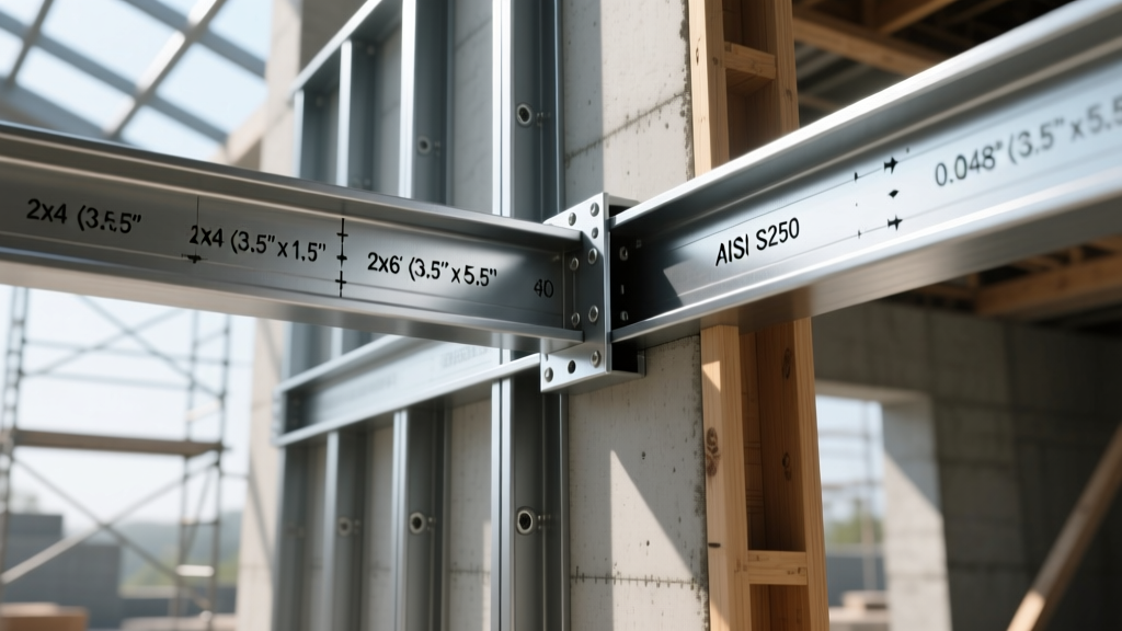
The Anatomy of Cold-Formed Steel Framing
Cold-formed steel (CFS) framing relies on strict dimensional standardization to ensure structural integrity, predictability in cost, and seamless integration with other building systems. Unlike wood framing, which suffers from natural warping and nominal-vs-actual size discrepancies, steel framing dimensions are exact. A 3-5/8-inch steel stud is precisely 3.625 inches deep. Understanding these physical dimensions, the industry-standard designation system, and thickness metrics is mandatory for structural engineers, framers, and estimators.
Every standard C-shaped steel stud consists of three primary dimensional components:
- Web Depth: The flat vertical section connecting the flanges. This dictates the overall depth of the wall cavity and the stud's bending capacity along its strong axis.
- Flange Width: The horizontal lips extending from the web. Flanges provide the bearing surface for drywall and sheathing, and their width directly impacts the stud's lateral torsional buckling resistance.
- Lip Return: The 90-degree bend at the outer edge of the flange, typically measuring 1/2-inch or 5/8-inch. The lip acts as a compression flange stiffener, preventing the flange from buckling inward under load.
Decoding the AISI Designation System
The American Iron and Steel Institute (AISI) and the Steel Framing Industry Association (SFIA) utilize a unified alphanumeric nomenclature to identify steel framing dimensions. Reading a manufacturer's label correctly eliminates guesswork on the job site.
- 362: Web depth in hundredths of an inch (3.62 inches, commonly called 3-5/8").
- S: Member type (S = Stud, T = Track, U = Channel, F = Furring).
- 162: Flange width in hundredths of an inch (1.62 inches, commonly called 1-5/8").
- 54: Minimum uncoated steel thickness in mils (54 mils = 0.054 inches, equivalent to 16-gauge).
By decoding this string, a framer knows instantly that the piece is a load-bearing stud with a 3-5/8-inch web, a 1-5/8-inch flange, and a 54-mil thickness, without needing to measure it manually.
Standard Steel Framing Dimensions Matrix
While custom roll-forming is possible for specialized projects, 95% of commercial and residential light-gauge steel framing utilizes standard web depths and flange widths. The matrix below outlines the most common dimensional profiles available from major manufacturers.
| Nominal Size | Actual Web Depth (in) | AISI Web Designation | Standard Flange Widths (in) | Primary Application |
|---|---|---|---|---|
| 1-5/8" | 1.625 | 162 | 1-1/4 | Shaft walls, chase walls, furring |
| 2-1/2" | 2.500 | 250 | 1-1/4, 1-5/8 | Non-load-bearing partitions |
| 3-5/8" | 3.625 | 362 | 1-5/8, 2 | Standard interior/exterior walls |
| 4" | 4.000 | 400 | 1-5/8, 2 | Plumbing walls, insulated exterior |
| 6" | 6.000 | 600 | 1-5/8, 2, 2-1/2 | Load-bearing exterior, tall partitions |
| 8" | 8.000 | 800 | 2, 2-1/2, 3 | Multi-story load-bearing, floor joists |
| 10" | 10.000 | 1000 | 2-1/2, 3 | Heavy load-bearing, long-span joists |
Track Dimensions and Stud Mating Tolerances
A critical edge case in steel framing dimensions is the relationship between the stud and the track (the U-shaped channel at the top and bottom of the wall). Tracks do not have lip returns, allowing studs to slide inside them. However, the track's physical web depth must be larger than the stud's web depth to accommodate the steel thickness and allow for installation tolerances.
For example, a 362 stud (3.625-inch web) does not fit into a track with a 3.625-inch web. It requires a track with an inside web depth of at least 3.75 inches, typically designated as a 400T (4-inch nominal track). When ordering materials, always verify that the track designation corresponds to the stud size it is meant to enclose, not the physical exterior dimension of the track itself.
Thickness: Mils vs. Gauges
While older construction documents may reference 'gauge' (e.g., 16-gauge, 20-gauge), the Cold-Formed Steel Engineers Institute (CFSEI) and modern building codes strictly mandate the use of mils (thousandths of an inch) or decimal inches for structural calculations. The gauge system is inherently flawed because a '16-gauge' wire diameter differs from a '16-gauge' sheet metal thickness.
Critical Specification Note: Always specify minimum uncoated steel thickness in mils on structural drawings. The galvanized coating (typically G60 or G90) adds roughly 1 to 1.5 mils to the total physical thickness, but structural capacity calculations must be based on the bare steel dimension.
Standard Thickness Equivalencies:
- 33 mils: ~20 gauge (Non-load-bearing partitions only)
- 43 mils: ~18 gauge (Light load-bearing, curtain walls)
- 54 mils: ~16 gauge (Standard load-bearing, exterior structural)
- 68 mils: ~14 gauge (Heavy load-bearing, multi-story)
- 97 mils: ~12 gauge (High-load columns, truss chords)
Real-World Tolerances and Installation Edge Cases
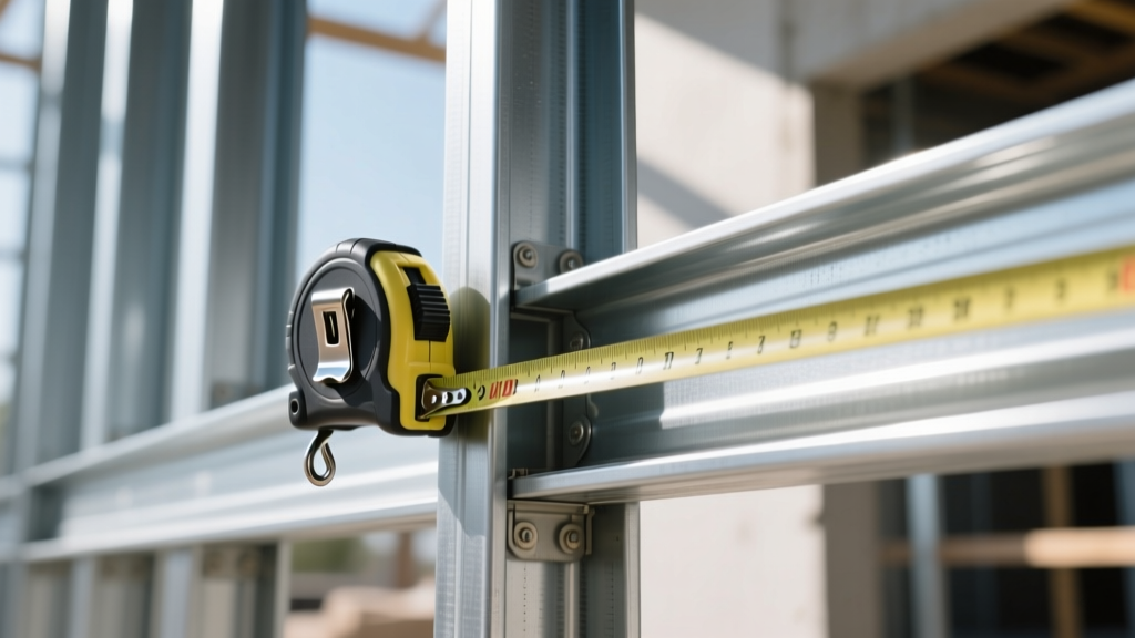
Manufacturing steel framing dimensions involves roll-forming coils through a series of dies. This process introduces minor, unavoidable deviations. The SFIA sets strict manufacturing tolerances that framers and inspectors must account for during layout and installation.
Camber, Bow, and Sweep Limits
- Camber (Bowing in the plane of the web): Maximum deviation of 1/8-inch per 10 feet of length. Excessive camber makes it impossible to align studs plumb without inducing stress into the drywall.
- Sweep (Bowing perpendicular to the web): Maximum deviation of 1/8-inch per 10 feet. Sweep is particularly problematic in load-bearing walls, as it introduces eccentric loading that drastically reduces the stud's axial capacity.
- Twist: Maximum deviation of 1/32-inch per inch of flange width. Twisted studs will not sit flat against the track web, resulting in poor screw engagement and compromised shear transfer.
When framing long corridors or elevator shafts, framers must 'crown' the studs (orienting the natural camber in the same direction) to prevent a wavy wall surface. If a stud exceeds the 1/8-inch per 10-foot sweep limit, it must be rejected or cut into shorter, non-critical blocking pieces.
Fastener Selection Based on Framing Dimensions
The physical thickness (mils) of the steel framing dictates the required fastener size. Using a screw that is too large for thin steel will strip the threads and destroy the connection's pull-over capacity. Using a screw too small for thick steel will result in 'burnout,' where the drill point melts the zinc coating and fails to penetrate the base metal.
| Steel Thickness (Mils) | Recommended Screw Size | Drill Point Type | Head Style |
|---|---|---|---|
| 33 to 43 mils | #8 or #10 | Standard Drill Point (#2) | Bugle Head (Drywall) or Pan Head (Steel-to-Steel) |
| 54 to 68 mils | #10 or #12 | Self-Drilling (#3 or #4 Point) | Hex Washer Head (HWH) or Pancake Head |
| 97+ mils | #12 or 1/4" | Heavy Duty Self-Drilling (#5 Point) | Hex Washer Head with neoprene seal |
For structural connections involving 54-mil or thicker steel, always utilize screws with a minimum #3 drill point to ensure clean penetration through both flanges without pre-drilling. When attaching gypsum board to 33-mil non-load-bearing studs, fine-thread #6 or #8 bugle head screws are required to prevent tearing the paper face of the drywall.
Written by
Marcus ChenMarcus Chen is a licensed structural engineer (PE) and building materials analyst with over 12 years of experience across residential, commercial, and industrial construction. He holds a Master of Science in Civil Engineering from UC Berkeley and spent six years at Thornton Tomasetti before transitioning to independent consulting and technical writing. Marcus specializes in material selection for seismic-prone regions, concrete reinforcement strategies, and lifecycle cost analysis. His work has been cited by the American Concrete Institute (ACI) and the Structural Engineers Association of California (SEAOC). When he is not on a job site or at his desk, you will find him hiking the Sierra Nevada or restoring a 1920s craftsman bungalow in Oakland, CA.
More from Marcus Chen
View all
Construction Cost
How Much Did the Eiffel Tower Cost to Build?
How much did the Eiffel Tower cost to build in 1889? We adjust for inflation and compare its budget to modern skyscraper construction.
Aug 4, 2026

Fire Resistance
What Is a Fire Resistant Material? Testing & Certification Guide
Discover what is a fire resistant material through ASTM and UL testing. Learn how fire ratings, certifications, and assemblies work in construction.
Aug 4, 2026

Construction Cost
How Much Did the Burj Khalifa Cost to Build?
How much did the Burj Khalifa cost to build? We break down the $1.5B project and extract 5 money-saving strategies for your next build.
Jul 30, 2026