Steel Framing Screws: Drill Points, Gauges & Technical Specs
Master steel framing screw specifications. Compare drill points, head styles, and gauge capacities for self-drilling and self-piercing fasteners.

The Engineering Anatomy of Steel Framing Screws
When assembling cold-formed steel (CFS) structures, selecting the correct steel framing screws is a structural imperative, not a matter of convenience. Unlike wood fasteners, screws designed for steel framing must overcome high shear strength, prevent galvanic corrosion, and manage heat dissipation during installation. The anatomy of these fasteners is highly specialized to address the unique failure modes associated with thin-gauge metals, typically ranging from 25-gauge (0.0179 inches) down to 10-gauge (0.1345 inches).
A standard steel framing screw consists of four critical zones: the head, the shank, the thread profile, and the drill point. The thread profile is particularly vital. Steel-to-steel connections require fine threads (typically 20 to 24 Threads Per Inch, or TPI) to maximize thread engagement in thin metal without stripping the pilot hole. Conversely, when attaching wood, OSB, or gypsum sheathing to steel studs, coarse threads (12 to 14 TPI) are required to pull the sheathing tight against the steel flange without tearing the substrate.
In industry catalogs, you will frequently see 'Type S' and 'Type S-12' designations. A Type S screw features a sharp, self-piercing point designed for pre-punched holes or ultra-thin gauges (25ga to 20ga). A Type S-12 screw features a self-drilling point (often called a Tek point) capable of drilling through steel up to 12-gauge thickness without a pre-drilled pilot hole.
Drill Point Classifications and Gauge Capacities
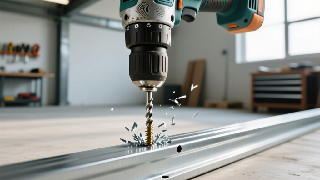
The drill point is the defining characteristic of a self-drilling steel framing screw. Using an undersized drill point for a specific steel thickness will cause the point to burn out before the threads engage, leading to fastener snapping or bit cam-out. Using an oversized drill point on thin gauge steel will create a hole larger than the thread root, resulting in zero pull-out resistance and immediate structural failure.
| Drill Point Size | Max Steel Thickness | Typical Application | Optimal RPM Range |
|---|---|---|---|
| #1 Point | Up to 18 Ga (0.0478') | Light gauge tracks, drywall to steel | 2,500 - 4,000 RPM |
| #2 Point | Up to 14 Ga (0.0747') | Standard stud-to-track, 20ga to 14ga connections | 1,800 - 2,500 RPM |
| #3 Point | Up to 10 Ga (0.1345') | Heavy gauge load-bearing studs, truss connections | 1,500 - 2,000 RPM |
| #4 Point | Up to 3/16' (0.1875') | Structural steel plates, thick flange splicing | 1,200 - 1,800 RPM |
| #5 Point | Up to 1/2' (0.5000') | Heavy structural beams, HSS tube steel | 1,000 - 1,500 RPM |
Head Profiles and Drive Systems
The head profile dictates how the screw distributes clamping force and interacts with the substrate. Selecting the wrong head profile can lead to pull-through in thin tracks or paper tearing in gypsum board.
Wafer Head (Low Profile)
Wafer heads feature a wide, flat bearing surface with a low-profile dome. This design is mandatory for steel-to-steel track connections where the screw head must not interfere with the insertion of vertical studs. The wide bearing surface distributes the clamp load over a larger area, preventing the screw from pulling through 25-gauge or 20-gauge track material. Most wafer head steel framing screws utilize a Phillips #2 or Square drive.
Bugle Head
Designed exclusively for attaching gypsum board or cementitious sheathing to steel framing. The curved underside of the bugle head smoothly depresses the paper face of the drywall without cutting or tearing it, allowing for seamless mudding. Bugle head screws for steel framing almost universally feature a fine thread and a sharp or #1 drill point.
Hex Washer Head (HWH)
Used for heavy-gauge structural connections, exterior sheathing, or attaching mechanical fixtures to steel studs. The integrated washer provides a secondary seal and immense bearing surface. HWH screws are driven with a 1/4' or 5/16' hex nut setter and are typically paired with #3 or #4 drill points for thick structural steel.
While Phillips #2 drives remain the industry standard for drywall and light-gauge framing due to bit availability, they are highly susceptible to cam-out when driving self-drilling screws into 14-gauge or thicker steel. For structural steel framing (12-gauge and below), specify screws with Torx (Star) or Square (Robertson) drives. These drives transfer torque axially, eliminating cam-out and preventing the destruction of the drill point before it penetrates the steel.
Installation Parameters: RPM, Torque, and Clutch Settings
Driving steel framing screws requires precise thermal management. The drill point must generate enough friction to melt and displace the steel, but not so much heat that it anneals (softens) the screw's hardened tip. According to technical data from manufacturers like Simpson Strong-Tie and ITW Buildex, RPM and clutch settings must be calibrated to the specific gauge and point size.
- High-Speed / Low-Torque (Drywall to Steel): Use a dedicated drywall screw gun set between 2,500 and 4,000 RPM. The depth-sensitive nose piece is critical here to prevent over-driving and breaking the gypsum paper. The clutch should be set to disengage immediately upon hitting the paper surface.
- Medium-Speed / Medium-Torque (Light Gauge Steel-to-Steel): For 20ga to 16ga studs using #2 point wafer head screws, set the drill to 1,800 - 2,500 RPM. Apply firm, continuous axial pressure. Release the trigger the exact moment the threads pull the joint tight; lingering will strip the internal threads cut into the thin steel.
- Low-Speed / High-Torque (Structural Steel): For 10ga and thicker using #3 or #4 points, drop the RPM to 1,200 - 1,800. High RPM on thick steel will instantly burn out the cutting wings of the drill point. Use an impact driver or a high-torque drill with a clutch setting of 15+ to ensure the threads fully tap the thick material.
Troubleshooting Common Fastener Failures
Field failures in steel framing usually trace back to a mismatch between the fastener specification and the installation tool settings. Use this decision matrix to diagnose site issues:
- Symptom: The screw spins freely after driving (Stripped Hole).
Cause: Over-driving or using a drill point too large for the gauge. The threads have reamed out the pilot hole.
Fix: Step down to a smaller drill point (e.g., from #3 to #2) or adjust the drill clutch to disengage earlier. - Symptom: The drill point burns out or snaps before penetrating.
Cause: RPM is too high, generating excessive heat and annealing the hardened tip, or insufficient axial pressure.
Fix: Reduce drill speed by 500 RPM and apply heavier, steady body weight behind the drill. Do not pulse the trigger. - Symptom: The screw head shears off (Torsional Failure).
Cause: The threads engage the bottom piece of steel before the drill point has fully cleared the top piece, creating a 'jacking' effect that snaps the shank.
Fix: Ensure the unthreaded shank length (the 'grip length') is longer than the combined thickness of the top substrate being fastened.
Industry Standards and Compliance
All steel framing screws utilized in commercial and load-bearing residential construction must comply with stringent material and performance standards. The primary governing standard in the United States is ASTM C1512, which dictates the mechanical properties, dimensional tolerances, and corrosion resistance requirements for steel framing fasteners. This standard mandates specific hardness levels (typically Rockwell C 50-58 for the drill point and C 38-45 for the shank) to ensure the screw can penetrate steel without becoming brittle enough to snap under shear loads.
Furthermore, structural connection designs utilizing these screws must adhere to the Cold-Formed Steel Engineers Institute (CFSEI) guidelines and the AISI S100 North American Specification for the Design of Cold-Formed Steel Structural Members. Engineers rely on the published pull-out and shear capacities of specific screw models—tested in accordance with ASTM C1512—to calculate the lateral bracing and diaphragm shear values of the overall steel framing system. Always verify that the selected fastener carries an ICC-ES Evaluation Report confirming its compliance with the specified building code cycle.
Written by
Priya KapoorPriya Kapoor is a real estate market analyst and construction economics researcher with expertise in housing affordability, development feasibility, and infrastructure investment. She holds a Master of Regional Planning from Cornell University and previously worked as a senior analyst at CBRE's Investment Properties group, where she modeled returns for $4B in mixed-use development pipelines. Priya now runs an independent research practice advising developers, municipalities, and REITs on construction cost forecasting and market timing. She publishes the quarterly "BuildMat Market Pulse" report tracking material price indices across 12 commodity categories. Based in Austin, TX, Priya serves on the board of Habitat for Humanity Austin and is a marathon runner.
More from Priya Kapoor
View all
Construction Cost
Cost to Build a 1600 Sq Ft Home in 2026: Full Breakdown
Accurate 2026 cost to build a 1600 sq ft home—material, labor, and regional pricing breakdowns included. Plan your budget with real-time estimates.
Aug 11, 2026
Wood & Lumber
Name the Types of Wood for Pressure Treatment and Preservation
Learn how to name the types of wood best suited for pressure treatment. Compare species treatability, chemical retention levels, and 2026 preservation costs.
Aug 4, 2026

Stone & Masonry
Stone Veneer Suppliers Lindenhurst: 2026 Cost Analysis
Analyze 2026 stone veneer costs in Lindenhurst, NY. Compare local supplier pricing, delivery fees, and Suffolk County installation labor rates.
Aug 4, 2026