Critical Steel Framing Details for Structural Load Paths
Master critical steel framing details for structural load paths. Explore hold-downs, fastener matrices, and failure modes for CFS and hot-rolled steel.

The Anatomy of a Structural Load Path
The structural integrity of any steel-framed building relies entirely on its connections. A 97-mil (12-gauge) cold-formed steel (CFS) stud possesses immense axial compressive strength, but without properly detailed track attachments and hold-downs, the assembly will fail under lateral loads. In structural applications, steel framing details dictate how gravity, wind, and seismic forces transfer from the roof diaphragm, through the shear walls, and down into the foundation.
Designing these load paths requires strict adherence to the Cold-Formed Steel Engineers Institute (CFSEI) guidelines and the American Iron and Steel Institute (AISI) S100 specification. Engineers must calculate not just the capacity of the framing members, but the exact shear and pull-over capacities of every fastener, clip, and anchor bolt in the system.
Critical Steel Framing Details in Practice
Translating engineering calculations into field-executable framing details requires specifying exact hardware, fastener schedules, and bearing conditions. Below are the most critical connection details in structural steel framing.
1. Shear Wall Hold-Downs and Anchor Bolts
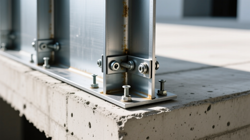
Shear walls resist lateral wind and seismic forces. The most critical detail in a steel shear wall is the chord stud hold-down, which prevents the wall from overturning. For multi-story structures, continuous rod tie-down systems (such as Simpson Strong-Tie's ATS or similar proprietary systems) are required to transfer cumulative overturning forces directly to the foundation.
- Anchor Bolt Specification: Use ASTM F1554 Grade 55 or Grade 105 anchor bolts, minimum 5/8-inch diameter, embedded at least 12 inches into the concrete foundation.
- Hold-Down Hardware: Specify heavy-duty hold-downs rated for the specific cumulative tension load. Ensure the bearing plate rests flush against the bottom track and concrete, utilizing hardened steel washers to prevent deformation under high tension.
- Shrinkage Compensators: In wood-concrete hybrid or multi-story CFS builds, install take-up devices (shrinkage compensators) at each floor level to maintain tension in the continuous rod as the building settles and materials dry.
2. Truss-to-Wall Uplift Connections
Roof uplift from wind events can easily exceed the dead load of a steel truss system. Standard gravity-bearing clips are insufficient. Structural steel framing details must incorporate proprietary hurricane ties or heavy-gauge clip angles that resist both vertical uplift and lateral displacement.
When attaching steel trusses to CFS top tracks, avoid relying solely on self-drilling screws through the thin track flange. Instead, detail a clip angle that wraps over the top track and fastens directly into the web of the wall stud using a minimum of four #12 structural screws per leg. This bypasses the weak track flange and transfers uplift directly into the vertical stud.
3. Web Stiffeners and Bearing Details
Cold-formed steel joists are highly susceptible to "web crippling"—a localized failure where the thin web of the CFS member buckles under concentrated bearing loads at supports or point loads. According to AISI S100, web stiffeners (also known as bearing stiffeners) are mandatory when the bearing length or concentrated load exceeds the unstiffened web capacity.
- Material Match: Web stiffeners must be cut from the same gauge and yield strength steel as the joist (typically ASTM A1003 Grade 50).
- Installation Detail: The stiffener must fit tightly against the inside radius of the joist web and flange. It is typically installed on both sides of the web and fastened with a staggered pattern of #10 or #12 self-drilling screws to prevent localized buckling.
4. Moment Frame Beam-to-Column Joints
For hot-rolled structural steel applications, moment frames provide lateral stability without the need for diagonal bracing or shear walls. The beam-to-column connection details in these frames are highly complex and strictly governed by the AISC Steel Construction Manual and AISC 358 prequalified connections.
A standard fully restrained (FR) moment connection requires complete joint penetration (CJP) groove welds on the beam flanges to transfer bending moments, paired with a shear tab welded to the column and bolted to the beam web to transfer shear forces. Field detailing must account for weld access holes (rat holes), backing bar removal, and non-destructive testing (NDT) of the flange welds to ensure ductile behavior during seismic events.
Fastener Selection Matrix for Structural Framing
Selecting the wrong fastener is the most common cause of connection failure in steel framing. The matrix below outlines standard fasteners, their governing ASTM standards, and their primary structural applications.
| Fastener Type | ASTM Standard | Nominal Shear Capacity | Primary Structural Application |
|---|---|---|---|
| #12 Self-Drilling Screw (Hex Washer Head) | ASTM C1512 | 800 - 1,200 lbs | CFS stud-to-track, heavy shear wall sheathing, clip angles |
| 1/2" A325 Hex Bolt | ASTM F3125 | 12,500+ lbs | Hot-rolled beam splices, heavy ledger attachments, moment frames |
| 5/8" Diameter Anchor Bolt | ASTM F1554 Gr 55 | 4,500+ lbs (Pullout) | Sill track to concrete foundation, shear wall hold-down bases |
| 3/8" Powder-Actuated Pin | ASTM F2277 | 600 - 900 lbs | Light-gauge non-structural track to concrete slab (interior partitions) |
Common Failure Modes in Steel Connections
Understanding how connections fail allows engineers and detailers to design against specific vulnerabilities. The following failure modes frequently appear in forensic investigations of steel framing failures:
When a clip angle or end plate is subjected to tension, the flexible legs of the steel can deform, creating a "prying" force at the edges. This prying action can amplify the tension load on the bolts or screws by 20% to 40%. To mitigate this, detail connections with thicker clip angles, add stiffener ribs, or move the fasteners closer to the center of the bending element.
In thin-gauge CFS (33 mil to 54 mil), the head of a self-drilling screw can pull through the connected sheet under high tension, or the steel can tear out around the screw shank in shear. Detailers must specify larger washer heads (e.g., 5/8-inch or 3/4-inch hex washer heads) and ensure edge distances are at least 1.5 times the screw diameter to prevent tear-out.
Field crews using high-torque impact drivers frequently over-tighten self-drilling screws, stripping the threads in the base steel and reducing the connection's shear capacity to near zero. Specifications must mandate torque-sensing screw guns that automatically clutch out when the screw is seated flush, preventing damage to the connection.
Code Compliance and Inspection Framework
Structural steel framing details must be verified during construction to ensure compliance with the International Building Code (IBC) and project-specific engineering drawings. Inspectors and site supervisors should utilize a rigid checklist for connection verification:
- Verify Material Grades: Check mill certificates to ensure CFS studs and tracks meet ASTM A1003 Grade 50 (50 ksi yield strength) for structural members, and hot-rolled sections meet ASTM A992.
- Fastener Audit: Randomly sample installed connections to verify the correct screw diameter, length, and drill point are being used. Ensure structural screws are not substituted with standard drywall or sheet metal screws.
- Hold-Down Tensioning: For continuous rod tie-down systems, verify that the manufacturer's specified installation torque is applied to the anchor nuts and that shrinkage compensators are properly engaged.
- Weld Inspection: For hot-rolled moment frames, ensure all CJP groove welds have been tested via ultrasonic or magnetic particle NDT by a certified third-party inspector prior to fireproofing or enclosure.
Mastering steel framing details requires moving beyond basic member sizing and focusing intensely on how forces transition through hardware, fasteners, and bearing surfaces. By specifying exact ASTM materials, utilizing prequalified connection geometries, and enforcing strict field installation protocols, structural engineers can deliver steel frames that perform reliably under extreme loading conditions.
For comprehensive connection design tables and software tools, refer to the Simpson Strong-Tie CFS Connectors catalog and the latest AISI S100 design examples.
Written by
Sarah WhitfieldSarah Whitfield is a chartered quantity surveyor (MRICS) and construction cost analyst with 15 years of experience in material pricing, procurement strategy, and project budgeting. She earned her degree in Construction Management from the University of Reading (UK) and has worked on projects ranging from $2M custom homes to $180M mixed-use developments across North America and Europe. Sarah currently leads cost estimating for BuildMat Insight, maintaining a proprietary database of 4,000+ material price points updated quarterly. She is a frequent contributor to RSMeans cost data panels and has presented at the International Cost Engineering Council (ICEC) congress. Based in Denver, CO, Sarah is an avid trail runner and volunteer mentor for Women in Construction.
More from Sarah Whitfield
View all
Wood & Lumber
What Are the Different Types of Wood? A Builder's Guide
Compare structural softwoods, finish hardwoods, and engineered lumber. Analyze Janka ratings, MOE values, and 2026 pricing for construction.
Aug 4, 2026
Walls & Panels
Steel Framing vs Wood Framing: Corrosion and Moisture Defense
Compare steel framing vs wood framing for moisture resistance. Learn about galvanized coatings, condensation risks, and corrosion protection strategies.
Jul 21, 2026
Stone & Masonry
How to Cut Stone Veneer: Wet Saw vs Grinder Comparison
Compare the best tools for cutting stone veneer. We review wet saws, angle grinders, and chop saws to help you achieve clean, chip-free cuts.
Jul 21, 2026