How Different Types of Wood Floors Impact Structural Integrity
Discover how different types of wood floors act as structural diaphragms. Compare shear capacities, mass timber systems, and fastener schedules.

The Hidden Structural Role of Wood Floor Assemblies
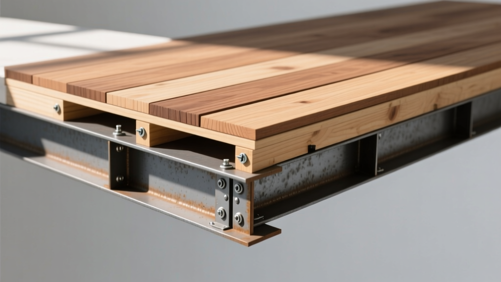
When architects and builders evaluate different types of wood floors, the focus typically defaults to aesthetic finish, durability, and foot-traffic resistance. However, from a structural engineering perspective, wood floor assemblies serve a critical secondary function: they act as horizontal diaphragms. In light-frame and mass timber construction, the floor diaphragm collects lateral loads from wind and seismic events and transfers them to vertical shear walls or braced frames. The specific material, thickness, and fastener schedule of the wood floor directly dictate the building's lateral force-resisting capacity.
Understanding how different types of wood floors perform under lateral and gravity loads is essential for optimizing material costs and ensuring code compliance under the International Building Code (IBC) and the American Wood Council's Special Design Provisions for Wind and Seismic (AWC SDPWS).
Comparing the Structural Capacity of Different Types of Wood Floors
Not all wood floors yield the same shear capacity. The transition from traditional solid-sawn lumber to engineered panels and mass timber has fundamentally altered diaphragm design. Below is a structural comparison matrix of common wood floor assemblies used in commercial and multi-family construction.
| Floor Assembly Type | Typical Material / Thickness | Allowable Shear (Unblocked) | Standard Fastener Schedule |
|---|---|---|---|
| Wood Structural Panel (Plywood) | 15/32" Structural I CDX | 230 plf | 8d common nails @ 6" o.c. edges |
| Wood Structural Panel (OSB) | 7/16" OSB Exposure 1 | 185 plf | 8d common nails @ 6" o.c. edges |
| Heavy Timber Plank Decking | 3" x 6" T&G Douglas Fir | 90 - 120 plf | 16d spikes + blind nailing |
| Cross-Laminated Timber (CLT) | 5-Ply (6.875" thick) | 400+ plf (Rigid) | Self-tapping screws / steel splines |
According to the APA - The Engineered Wood Association, Structural I plywood provides the highest baseline shear capacity among conventional panelized floors due to its cross-grain lamination and lack of core voids. However, when lateral demands exceed 230 pounds per linear foot (plf) on unblocked diaphragms, engineers must either specify thicker panels, reduce nail spacing to 4" or 2.5" on center, or introduce blocking at all panel edges to achieve capacities up to 870 plf.
Heavy Timber and Mass Timber Floor Systems
When evaluating different types of wood floors for exposed-ceiling applications or Type IV (Heavy Timber) construction, structural decking and mass timber panels replace concealed plywood subfloors.
Traditional Plank Decking
Heavy timber plank decking (typically 2" to 4" thick tongue-and-groove lumber) spans directly between primary glulam or steel beams. Structurally, 3x6 T&G Douglas Fir-Larch decking can span up to 12 feet under standard 40 psf live loads. However, its diaphragm shear capacity is severely limited compared to plywood because the planks only interlock at the tongue-and-groove joints. Under severe seismic loading, the planks tend to separate, requiring the addition of a structural topping slab or a secondary layer of plywood to act as the primary lateral diaphragm.
Cross-Laminated Timber (CLT) Floor Panels
CLT represents a paradigm shift in wood floor engineering. A 5-ply CLT panel (approximately 6.875 inches thick) acts as a two-way spanning slab capable of clear spans exceeding 25 feet without intermediate beams. Because the panels are manufactured as massive, dimensionally stable monoliths, CLT floors function as highly rigid diaphragms. Panel-to-panel connections utilizing internal steel splines and fully threaded self-tapping screws (such as the ASSY Ecofast series) allow the floor to transfer massive shear forces with minimal deformation. The WoodWorks Resource Library provides extensive case studies demonstrating how CLT floor diaphragms eliminate the need for interior shear walls in mid-rise commercial buildings.
Critical Fastener Schedules and Edge Nailing
The structural integrity of panelized wood floors is entirely dependent on the fastener schedule. The sheathing panels themselves rarely fail in shear; failure almost always occurs at the nail or staple connections pulling through the panel edge. For structural applications, builders must adhere to strict nailing protocols:
- Nail Type: 8d common nails (0.131" diameter, 2.5" length) are the baseline for structural diaphragms. Box nails or finish nails lack the shear strength and withdrawal resistance required by code.
- Edge vs. Field Spacing: Fasteners at the panel edges (where shear transfer is highest) are typically spaced at 4" or 6" on center, while field nailing (interior supports) is spaced at 12" on center.
- Edge Distance: Nails must be driven a minimum of 3/8" from the panel edge to prevent splitting the plywood or OSB veneers, which instantly compromises the connection's load capacity.
- Pneumatic vs. Hand Nailing: While pneumatic nailers are standard, over-driven nails (where the head breaks the surface veneer) can reduce diaphragm shear capacity by up to 20%. Structural inspectors must verify that nail heads are flush, not countersunk.
Deflection Limits and Vibration Control in Long Spans
When selecting different types of wood floors for long-span applications (such as open-concept multi-family corridors or commercial lobbies), bending stress and shear stress are rarely the governing design criteria. Instead, floor vibration and live-load deflection dictate the required joist depth and sheathing thickness.
"In residential and light-commercial wood framing, a floor system designed purely for code-minimum L/360 deflection will often fail the human perception test for vibration. Adding a 1-1/2" layer of gypsum underlayment or utilizing engineered I-joists with higher stiffness (EI) values is often more cost-effective than simply increasing the depth of solid-sawn lumber."
To mitigate footfall-induced vibration, structural engineers target a fundamental natural frequency ($f_n$) greater than 15 Hz. Thickening the wood structural panel subfloor from 3/4" to 7/8" or 1-1/8" (such as APA Rated Sturd-I-Floor) significantly increases the composite stiffness of the floor assembly, dampening high-frequency vibrations without requiring deeper framing members.
Decision Framework: Selecting the Right Floor for Lateral Loads
To systematically choose the correct wood floor assembly for a structural project, follow this four-step engineering framework:
- Calculate Diaphragm Shear Demand: Run the lateral load analysis to determine the maximum shear (plf) at the critical diaphragm lines. If the demand is under 230 plf, standard 15/32" Structural I plywood with 6" edge nailing is sufficient.
- Evaluate Blocking Requirements: If shear demands exceed unblocked capacities, determine if adding 2x blocking at all panel edges is more economical than upgrading to a thicker panel or closer nail spacing.
- Check Chord Forces: The perimeter framing (chords) must resist the bending moment generated by the diaphragm. Verify that the continuous rim board or double top plate has adequate tension capacity, and specify steel strap ties at splice locations.
- Assess Shrinkage and Moisture: For multi-story wood buildings, account for cross-grain shrinkage in solid lumber framing. Specify engineered wood joists (I-joists) or shrinkage-compensating hardware to prevent the wood floor diaphragm from warping and losing its fastener grip over the building's lifespan.
By treating wood floors as integral structural diaphragms rather than mere walking surfaces, engineers and builders can optimize material usage, ensure robust seismic performance, and fully leverage the structural capabilities of modern timber products.
Written by
James ThorntonJames Thornton is a construction industry veteran with 25 years of hands-on experience in wood framing, lumber grading, and residential building codes. He started as a framing carpenter in rural Oregon, earned his ICC Residential Building Inspector certification, and eventually became a senior plan reviewer for the City of Portland Bureau of Development Services. James holds a B.S. in Wood Science & Technology from Oregon State University and is a certified lumber grader through the West Coast Lumber Inspection Bureau (WCLIB). He has inspected over 3,000 residential construction sites and authored the city's internal guide on advanced framing techniques (2x6 at 24" O.C.). James lives in Bend, OR, where he builds custom timber-frame cabins and competes in lumberjack sports.
More from James Thornton
View all
Insulation
Best Home Insulation Materials: Complete 2026 Guide
Compare top home insulation materials for 2026. Find R-values, installed costs per square foot, and best uses for fiberglass, spray foam, and mineral wool.
Aug 4, 2026

Sustainable Building
Certify Your Green Building Material for LEED and WELL
Step-by-step guide to certifying a green building material for LEED v5 and WELL v2. Master EPDs, HPDs, and VOC limits for 2026 project specifications.
Aug 4, 2026

Stone & Masonry
Veneer Stacked Stone Panels: Interior Design & Style Showcase
Discover how veneer stacked stone panels transform interiors. Explore modern design profiles, material pairings, and technical installation specs.
Aug 4, 2026