How to Diagnose Issues Using Foundation Building Materials Photos
Learn to diagnose structural damage by analyzing foundation building materials photos. Identify crack patterns, spalling, and material failure.

The Diagnostic Power of Visual Documentation
Remote structural assessment has evolved significantly. By analyzing high-resolution foundation building materials photos, engineers and inspectors can identify early-stage material degradation, differential settlement, and hydrostatic pressure failures before they require invasive demolition. However, a photograph is only diagnostically valuable if the viewer understands the material science behind the visible anomalies. Interpreting visual evidence requires distinguishing between superficial curing defects and catastrophic shear failures, a skill rooted in understanding how specific foundation materials react to environmental stressors.
Decoding Concrete Spalling and Rebar Corrosion
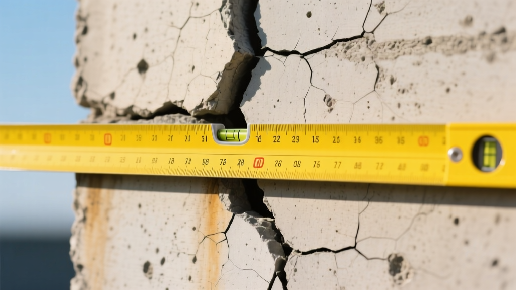
Poured concrete and concrete block foundations frequently exhibit surface deterioration that mimics structural failure. When reviewing foundation building materials photos, the primary objective is to determine the depth and cause of the spalling.
Surface scaling (flaking of the top 1/8 inch) is typically a freeze-thaw cycle issue caused by air-entrainment deficiencies during the original pour. However, if the photos reveal linear cracking parallel to the ground or bulging concrete, you are likely witnessing rust jacking. When embedded steel rebar corrodes due to chloride ion ingress or carbonation, the iron oxide expands up to seven times its original volume. This exerts internal tensile forces exceeding 10,000 PSI, delaminating the concrete cover. Photos showing exposed, heavily oxidized rebar mandate immediate structural intervention.
To accurately assess concrete defects remotely, refer to the American Concrete Institute (ACI) Standards for visual evaluation criteria. Look for the following visual markers in the imagery:
- Popouts: Small, conical fractures (usually 1/2 to 2 inches wide) caused by expansive aggregates like chert absorbing moisture.
- D-Cracking: A series of fine cracks parallel to joints and edges, indicating that the coarse aggregate itself is failing under freeze-thaw conditions.
- Efflorescence vs. Leaching: White, powdery deposits (efflorescence) indicate active moisture migration carrying soluble salts to the surface. Thick, stalactite-like calcium carbonate deposits (leaching) indicate a chronic, active water leak through a structural void.
Masonry and CMU Warning Signs
Concrete Masonry Unit (CMU) foundations fail differently than poured concrete due to the presence of mortar joints. The mortar is typically the weakest link in the assembly. When analyzing foundation building materials photos of block walls, crack morphology is the most reliable indicator of the underlying force vector.
| Crack Pattern | Material Behavior | Probable Root Cause | Urgency Level |
|---|---|---|---|
| Horizontal mid-wall | Flexural failure of mortar joints | Lateral hydrostatic pressure from saturated backfill | Critical |
| Stair-step (stepped) | Shear failure along weakest path | Differential settlement at the footing level | High |
| Vertical center | Tensile splitting | Thermal expansion/contraction or wall bowing | Moderate |
| Hairline map cracking | Surface shrinkage | Rapid moisture loss during mortar curing | Low (Cosmetic) |
According to the InterNACHI Standards of Practice, any horizontal crack in a CMU basement wall accompanied by inward deflection greater than 1/2 inch requires immediate evaluation by a licensed structural engineer, as it signals impending collapse from soil pressure.
Evaluating Pier and Beam Materials from Images
Crawl space foundations rely on a matrix of piers, beams, and joists. Diagnosing these systems via foundation building materials photos requires a keen eye for biological and chemical degradation that compromises load-bearing capacity.
Wood Pier and Post Indicators
When inspecting photos of timber posts resting on concrete footings, look for the soil-to-wood interface. If the photos show wood embedded directly into soil or resting on unsealed concrete, probe for rot. Brown cubical rot manifests as deep, cross-grained checking (cracking) where the wood crumbles into cube-like chunks, indicating severe cellulose destruction by fungi. White rot appears fibrous and spongy, breaking down the lignin. Both require immediate post replacement with pressure-treated timber (minimum UC4A retention level for ground contact) or galvanized steel lally columns.
Steel Pier Oxidation Scales
Helical and push piers are manufactured from high-strength steel. Surface rust is expected, but structural compromise occurs when section loss exceeds 10%. In photos, look for lamellar rust—thick, flaky scales of iron oxide that can be chipped away with a screwdriver. If the photos reveal pitting (localized, deep craters in the steel) rather than uniform surface oxidation, the load-bearing capacity of the pier shaft is severely compromised.
Lighting, Angles, and Scale: Taking Diagnostic-Grade Photos
The accuracy of a remote diagnosis relies entirely on the quality of the visual data. Homeowners and junior inspectors often capture images that obscure the very defects they are trying to document. Follow this protocol to capture diagnostically viable foundation building materials photos:
- Establish Scale: Always place a reference object in the frame. A standard US Quarter coin (0.955 inches / 24.26 mm diameter) is ideal for crack width assessment. For larger spalled areas, use a standard 12-inch ruler or a dedicated crack gauge card.
- Utilize Raking Light: To document surface spalling, delamination, or bowing, do not use direct, head-on flash. Instead, position a light source (or wait for the sun) at a sharp, oblique angle to the wall. This "raking light" casts shadows in microscopic depressions, revealing surface anomalies invisible in flat lighting.
- The 90-Degree Rule: To measure crack width accurately, the camera lens must be perfectly perpendicular (90 degrees) to the wall surface. Angled shots introduce parallax error, making cracks appear narrower or wider than they actually are.
- Capture the Macro and the Micro: Take a wide shot showing the crack's relationship to the entire wall and adjacent corners, followed by a macro shot with the scale reference. This context is vital; a 1/4-inch crack at a corner intersection implies differential settlement, while the same width in the center of a long wall implies thermal or shrinkage stress.
Historical Photo Comparison and Deflection Rates
A single photograph provides a snapshot; a timeline provides a diagnosis. When evaluating foundation building materials photos over time, structural engineers calculate the deflection rate. If a basement wall bowed inward 1/4 inch over ten years, it is a slow, manageable creep often stabilized with carbon fiber straps or steel I-beams. If historical photos show the wall bowed an additional 1/2 inch in just six months, the soil's active pressure has exceeded the wall's yield point, necessitating immediate exterior excavation and helical tieback installation.
Pro Tip for 2026 Assessments: Modern smartphone LiDAR scanners (available on Pro-tier devices) allow users to generate highly accurate 3D point clouds of foundation walls. Exporting these meshes alongside standard 2D foundation building materials photos allows remote engineers to measure exact volumetric deflection and calculate load eccentricity without visiting the site.
When Photo Evidence Mandates an In-Person Visit
While visual analysis is a powerful triage tool, certain conditions visible in photos immediately trigger the need for an on-site structural engineer equipped with soil borings and laser levels. Escalate the assessment if the photos reveal:
- Crack Widths Exceeding 3/8 Inch (9.5mm): This generally indicates that the foundation has moved beyond the elastic limit of the materials.
- Shear Displacement: If one side of a crack is visibly offset from the other (a lip you can catch your fingernail on), the footing has fractured or rotated.
- Water Intrusion at the Floor-to-Wall Joint: While often a waterproofing issue, if accompanied by upward heaving of the interior slab, it indicates a failed drain tile system and potential hydrostatic uplift threatening the slab's integrity.
Mastering the interpretation of foundation building materials photos transforms a simple visual inspection into a rigorous, data-driven diagnostic process, saving property owners thousands of dollars in unnecessary exploratory demolition while ensuring critical structural threats are never overlooked.
Written by
David NakamuraDavid Nakamura is a licensed architect (AIA) and construction technology writer focused on sustainable building methods, mass timber engineering, and high-performance building envelopes. He holds a Master of Architecture from the University of Washington and is a certified Passive House Consultant (CPHC). David spent eight years at the Seattle firm Mithun, where he led the design of three LEED Platinum projects, before founding his own practice specializing in net-zero residential design. He serves on the editorial advisory board of GreenBuilder Magazine and has authored peer-reviewed papers on cross-laminated timber (CLT) connections for the Journal of Structural Engineering. In his spare time, David teaches woodworking at Pratt Fine Arts Center and kayaks the Puget Sound.
More from David Nakamura
View all
Construction Cost
Labor Cost to Build a Deck Per Sq Ft: 2026 Installation Guide
Discover the exact labor cost to build a deck per sq ft in 2026. This installation guide breaks down contractor rates, complexity factors, and hidden fees.
Aug 4, 2026

Construction Cost
How Much Does It Cost to Build a 3 Bedroom House? Financing Guide
Learn exactly how much it costs to build a 3 bedroom house and explore 2026 financing options, construction loan types, and budget frameworks for your build.
Aug 4, 2026
Construction Cost
Cost to Build a Tennis Court: 2026 Guide
How much does it cost to build a tennis court in 2026? Breakdowns for asphalt, concrete, and synthetic surfaces plus fencing and lighting.
Jul 30, 2026