Selection Framework: Choosing the Right Types of Pile Foundation
Master our selection framework to choose between end-bearing, friction, and helical types of pile foundation based on soil, load, and site constraints.

The Core Selection Matrix: Load vs. Soil Stratigraphy
Selecting the appropriate deep foundation system requires moving beyond generic soil classifications and applying a rigorous load-transfer framework. The fundamental geotechnical equation for ultimate pile capacity is Qu = Qp + Qs, where Qp represents end-bearing (point resistance) and Qs represents shaft friction (skin friction). When evaluating different types of pile foundation, structural engineers must first determine which component of this equation will dominate the load transfer based on the site's subsurface stratigraphy.
Decision Node 1: End-Bearing vs. Friction Dominance
- End-Bearing Piles (Qp Dominant): Selected when a dense, incompressible stratum (such as bedrock, dense glacial till, or very stiff overconsolidated clay) exists at a drivable depth (typically 40 to 120 feet). These piles act as structural columns. If the bearing stratum is sloped or highly fractured, end-bearing capacity drops precipitously, requiring a transition to friction piles or micropiles.
- Friction Piles (Qs Dominant): Mandated when no hard stratum is reachable within 150 feet, common in deep alluvial deposits or soft marine clays. Capacity is derived entirely from the adhesion and friction along the pile shaft. To maximize Qs, engineers select piles with high surface-area-to-volume ratios, such as closed-end pipe piles or fluted precast concrete sections.
Material Selection Framework: Concrete, Steel, or Timber?
Once the load-transfer mechanism is established, the material selection must align with structural demand, corrosion exposure, and driving stresses. Below is a comparative matrix for the most common driven pile materials utilized in commercial and heavy civil projects.
| Material Type | ASTM Standard | Typical Dimensions | Est. Cost per LF (2026) | Primary Failure Mode / Limitation |
|---|---|---|---|---|
| Precast Prestressed Concrete (PPC) | ASTM C39 / PCI MNL-116 | 14x14 in. to 30x30 in. square | $65 - $115 | Tensile cracking during driving; splicing is difficult and expensive. |
| Steel H-Piles | ASTM A572 Gr. 50 | 10x42 to 14x117 (weight/ft) | $45 - $85 | Corrosion in high-sulfate soils; low lateral bending resistance. |
| Open-End Steel Pipe Piles | ASTM A252 Gr. 3 | 12 in. to 48 in. O.D. | $70 - $140 | Soil plugging during driving; requires internal cleaning and concrete fill. |
| Timber (Southern Yellow Pine) | ASTM D25 | 8 in. to 12 in. butt diameter | $35 - $60 | Decay above groundwater table; low axial capacity (max ~50 tons). |
Site Constraint Decision Tree: When to Use Helical or Micropiles
Traditional driven piles are often disqualified by site constraints such as low headroom, severe vibration limits, or restricted access. In these scenarios, the selection framework shifts toward specialized types of pile foundation like helical piles and micropiles.
Helical Piles for Light-to-Medium Tension and Compression
Helical piles are installed via rotary torque rather than impact driving, making them ideal for vibration-sensitive environments (e.g., adjacent to historic masonry or active hospital wings). According to the Deep Foundations Institute (DFI) Helical Pile Committee, the design relies heavily on the torque-to-capacity correlation: Qu = Kt × T, where Kt is an empirical torque factor and T is the installation torque. They are limited to axial loads generally under 100 tons and are unsuited for sites with dense cobbles or shallow bedrock that prevents helix advancement.
Micropiles for High-Capacity Restricted Access
When headroom is less than 12 feet and design loads exceed 150 tons, micropiles (typically 5 to 12 inches in diameter) are the default choice. Classified by the Federal Highway Administration (FHWA) into Types A through D based on grouting methods, Type D (pressure-grouted) micropiles provide the highest friction capacity in marginal soils. Expect mobilization costs to be high, but the per-foot installation in tight urban footprints justifies the premium.
Economic Modeling: Driven vs. Bored (Drilled) Installation
The choice between displacement (driven) and replacement (bored/drilled shafts) fundamentally alters the project's economic model and risk profile.
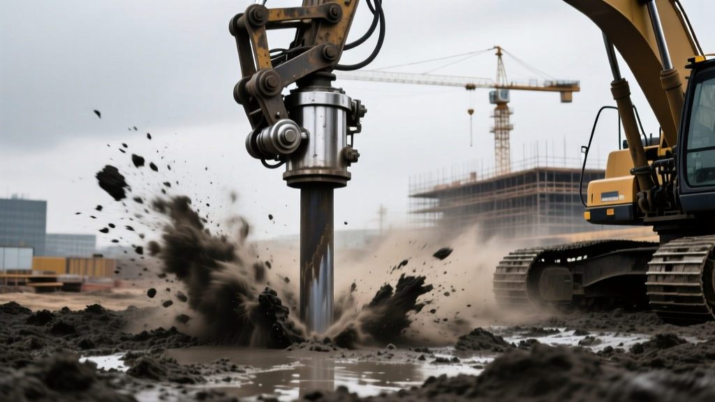
- Driven Piles (Displacement): Offer the distinct advantage of verifiable capacity during installation. Using Pile Driving Analyzers (PDA) per ASTM D4945, engineers can confirm capacity on every single pile in real-time. The risk of a 'defective pile' is near zero. However, mobilization for large impact hammers (e.g., ICE or APE vibratory hammers, or Delmag diesel hammers) can exceed $40,000, making driven piles uneconomical for projects requiring fewer than 50 piles.
- Drilled Shafts (Replacement): Eliminate vibration and noise, and can be socketed deep into rock. However, they carry a high risk of construction defects such as necking, soft toes, or concrete segregation during tremie placement. Mandatory cross-hole sonic logging (CSL) or thermal integrity profiling (TIP) adds $800 to $1,500 per shaft for quality assurance.
Geotechnical Red Flags: Failure Modes to Engineer Out
A robust selection framework must anticipate non-obvious failure modes that standard static load testing might miss.
Downdrag (Negative Skin Friction): If piles are driven through a recently placed fill or a consolidating soft clay layer, the settling soil will drag the pile downward, inducing massive compressive stresses that can exceed the structural capacity of the pile itself before any structural load is even applied. Mitigation requires applying a bituminous slip coating to the pile shaft through the consolidating zone.
- Liquefaction-Induced Buckling: In seismic zones, loose saturated sands lose shear strength during an event. End-bearing piles passing through these layers lose their lateral support, behaving as unbraced columns. Engineers must increase the pile section modulus or specify larger diameter pipe piles filled with reinforced concrete to resist P-Delta effects.
- Scour in Marine/Riparian Environments: For bridge piers, the top 15 to 30 feet of soil may be eroded during a 100-year flood event. The pile selection must treat this depth as 'unbraced length' for lateral load analysis, heavily favoring large-diameter open-end pipe piles driven to deep refusal.
Summary Checklist for Structural Engineers
Before finalizing the foundation bid documents, verify the following parameters against your selected pile type:
- [ ] Load Testing Protocol: Have you specified static load testing per ASTM D1143 for the preliminary test pile to validate the geotechnical report's friction angles?
- [ ] Driving Stresses: For PPC piles, have you run a WEAP (Wave Equation Analysis of Piling) to ensure compressive driving stresses do not exceed 85% of the concrete's compressive strength?
- [ ] Corrosion Allowance: Have you added the requisite sacrificial steel thickness (typically 1/16 inch per side) for H-piles in soils with pH < 5.5 or high electrical conductivity?
- [ ] Splice Integrity: If piles require splicing to reach refusal, are the splice connections (e.g., mechanical interlocking or full-penetration welds) rated for the maximum tensile uplift forces anticipated during seismic overturning?
By systematically filtering project parameters through this framework—matching stratigraphy to load transfer, aligning materials with environmental exposure, and mitigating installation risks—engineers can confidently specify the most cost-effective and structurally resilient deep foundation system.
Written by
David NakamuraDavid Nakamura is a licensed architect (AIA) and construction technology writer focused on sustainable building methods, mass timber engineering, and high-performance building envelopes. He holds a Master of Architecture from the University of Washington and is a certified Passive House Consultant (CPHC). David spent eight years at the Seattle firm Mithun, where he led the design of three LEED Platinum projects, before founding his own practice specializing in net-zero residential design. He serves on the editorial advisory board of GreenBuilder Magazine and has authored peer-reviewed papers on cross-laminated timber (CLT) connections for the Journal of Structural Engineering. In his spare time, David teaches woodworking at Pratt Fine Arts Center and kayaks the Puget Sound.
More from David Nakamura
View all
Construction Cost
Labor Cost to Build a Deck Per Sq Ft: 2026 Installation Guide
Discover the exact labor cost to build a deck per sq ft in 2026. This installation guide breaks down contractor rates, complexity factors, and hidden fees.
Aug 4, 2026
Construction Cost
How Much Does It Cost to Build a 3 Bedroom House? Financing Guide
Learn exactly how much it costs to build a 3 bedroom house and explore 2026 financing options, construction loan types, and budget frameworks for your build.
Aug 4, 2026
Construction Cost
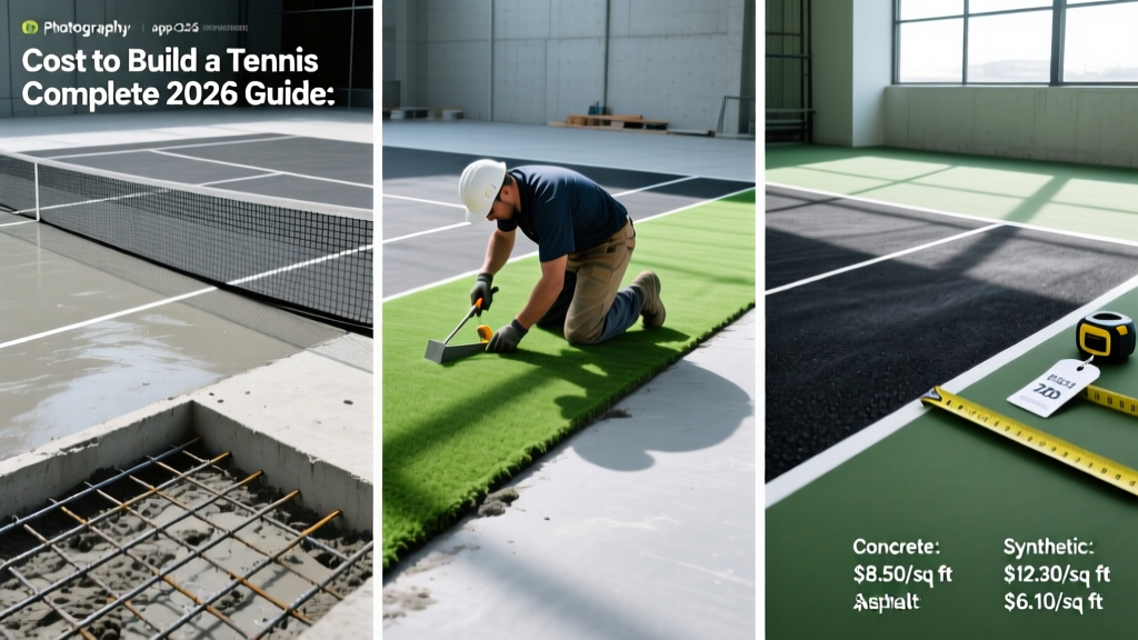
Cost to Build a Tennis Court: 2026 Guide
How much does it cost to build a tennis court in 2026? Breakdowns for asphalt, concrete, and synthetic surfaces plus fencing and lighting.
Jul 30, 2026