Different Types of Foundation for Houses: A Structural Analysis
Analyze the structural mechanics, load paths, and soil interactions of different types of foundation for houses to prevent differential settlement.

The Mechanics of Load Transfer in Residential Foundations
Foundation engineering is fundamentally an exercise in load path management and soil mechanics. The primary structural objective is to transfer dead loads (the weight of the structure), live loads (occupants and furnishings), and lateral loads (wind and seismic forces) into competent soil strata without exceeding the allowable bearing capacity or triggering differential settlement. When evaluating the different types of foundation for houses, structural engineers rely on geotechnical data—specifically the Standard Penetration Test (SPT) N-values and Atterberg limits—to dictate the geometry, reinforcement, and concrete specifications of the substructure.
As of 2026, advancements in concrete admixtures and high-strength steel have shifted standard practices, allowing for thinner, more resilient foundation elements that resist the increasing frequency of extreme moisture cycles and expansive soil movements.
Structural Breakdown of Different Types of Foundation for Houses
Selecting a foundation system requires matching the structural load profile to the site's geotechnical constraints. Below is a structural analysis of the primary residential foundation systems.
1. Monolithic Slab-on-Grade (Conventional vs. Post-Tensioned)
Slab-on-grade foundations distribute structural loads across a continuous footprint. They are categorized into two distinct structural systems:
- Conventional Reinforced Slabs: Typically utilize a 4-inch nominal slab thickened to 12-24 inches at the perimeter and interior load-bearing walls. Reinforcement consists of #4 (1/2-inch) Grade 60 rebar placed at 18 inches on center (OC) in the thickened edges. This system requires a subgrade with a high bearing capacity (minimum 2,000 psf) and low plasticity.
- Post-Tensioned (PT) Slabs: Engineered for highly expansive clays (CH soils) with a Plasticity Index (PI) exceeding 25. PT slabs utilize 270 ksi low-relaxation steel strands housed in plastic ducts, stressed to an effective prestress of 33 to 50 ksi after concrete curing. This introduces a compressive force into the concrete, neutralizing tensile stresses caused by soil swelling. As of 2026, PT material and stressing costs average $1.25 to $1.55 per square foot, making it highly cost-effective compared to deep pier systems in regions like Texas and Colorado.
2. T-Shaped Frost Wall and Crawlspace Foundations
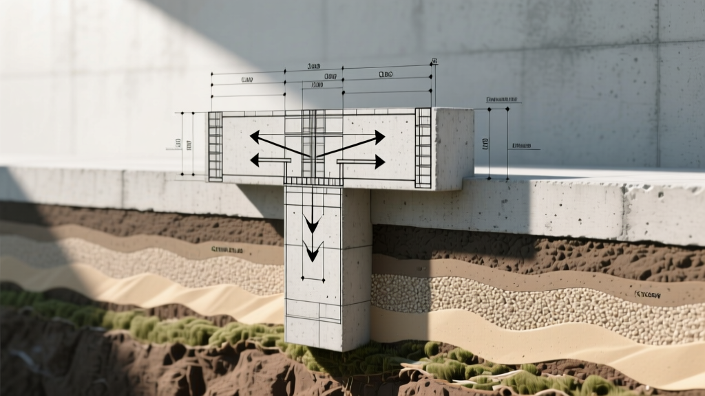
In climates where the ground freezes, foundations must extend below the frost line to prevent frost heave—a phenomenon where ice lenses form in the soil, generating upward hydrostatic pressures that can exceed 10,000 psf. The T-shaped foundation utilizes a continuous concrete footing that spreads the point loads from the stem wall over a wider soil area.
According to the International Residential Code (IRC) Chapter 4, footings must extend a minimum of 12 inches below undisturbed soil and below the local frost depth, with footing widths calculated based on the tributary load divided by the allowable soil bearing pressure.
Structurally, the stem wall acts as a continuous beam spanning between soil bearing points. In seismic zones, these walls require continuous vertical rebar tied into the footing dowels to resist shear forces and prevent brittle failure during lateral ground acceleration.
3. Drilled Concrete Piers with Grade Beams
When surface soils possess inadequate bearing capacity or exhibit extreme volumetric changes (expansive clays), loads must be bypassed and transferred to deeper, stable strata or bedrock. Drilled piers (caissons) are cast-in-place concrete columns drilled to depths of 15 to 40 feet.
- End-Bearing Piers: Transfer loads directly to bedrock or dense glacial till. The structural capacity is governed by the compressive strength of the concrete (typically 4,000 psi) and the bearing capacity of the rock.
- Friction Piers: Rely on the skin friction between the concrete shaft and the surrounding soil. Engineers may specify "belled" piers—where the base is mechanically enlarged to 2.5 times the shaft diameter—to artificially increase the end-bearing surface area in stiff clays.
The grade beam spanning between piers must be designed with a structural void (typically a 2-inch compressible void form) beneath it to prevent expansive soils from pushing upward on the beam and inducing negative bending moments.
4. Insulated Concrete Form (ICF) Basements
Basement foundations must resist immense lateral earth pressure and hydrostatic loads. ICF walls, composed of a 5.5 to 7.5-inch concrete core sandwiched between expanded polystyrene (EPS) foam, provide excellent structural rigidity. The concrete core is typically reinforced with #5 vertical rebar at 24 inches OC and #4 horizontal rebar at 16 inches OC. The structural design must account for the Rankine active earth pressure theory, ensuring the wall thickness and reinforcement can resist the parabolic load distribution of the retained soil without excessive deflection.
Soil Bearing Capacity and Foundation Selection Matrix
The geotechnical profile dictates the structural viability of foundation types. The following matrix aligns soil classifications with optimal foundation systems and highlights primary structural risks.
| Soil Classification (USCS) | Typical Bearing Capacity (psf) | Optimal Foundation System | Primary Structural Risk |
|---|---|---|---|
| Dense Sand / Gravel (GW, GP) | 4,000 - 6,000 | Conventional Slab, T-Shaped Footing | Scour, liquefaction in seismic zones |
| Stiff Clay (CL, CH) | 1,500 - 2,500 | Post-Tensioned Slab, Drilled Piers | Differential heave, shrinkage cracking |
| Soft Silt / Organic (ML, OL) | 500 - 1,000 | Deep Friction Piers, Helical Piles | Consolidation settlement, punch-through |
| Bedrock / Hardpan | 10,000+ | End-Bearing Piers, Rock Anchors | Excavation difficulty, lateral sliding |
Note: Always verify site-specific bearing capacities using the USDA Web Soil Survey and localized geotechnical boring logs.
When utilizing isolated pad footings or deep piers supporting concentrated column loads, engineers must calculate the punching shear stress at the critical perimeter (located at d/2 from the column face). If the shear stress exceeds the concrete's capacity (typically 4 * √f'c), the column will literally punch through the footing. Mitigation requires increasing footing depth or adding shear stud reinforcement.
Critical Failure Modes and Structural Mitigation
Understanding how foundations fail is critical for structural analysis. The most common catastrophic failure modes include:
- Differential Settlement: Occurs when one section of the foundation settles more than another, inducing severe torsional and bending stresses in the superstructure. Mitigation involves stiffening the foundation (using grade beams or PT cables) to bridge over localized soft spots, ensuring the deflection ratio (Δ/L) remains below 1/360.
- Overturning from Lateral Loads: High winds or seismic events generate overturning moments. For shallow foundations, the resisting moment is provided by the dead weight of the structure and the soil bearing on the toe of the footing. If the factor of safety against overturning drops below 1.5, engineers must increase the footing mass or utilize deep tension piers to anchor the structure.
- Hydrostatic Uplift: In areas with high water tables, the buoyant force of groundwater can exceed the dead load of a basement structure, causing it to float or crack. Structural mitigation requires hydrostatic relief valves in the slab and designing the basement walls to resist inward bending from external water pressure.
Engineering Decision Framework for 2026 Construction
To systematically select the correct foundation, structural engineers and builders should follow this sequential decision framework:
- Geotechnical Characterization: Obtain a Phase I site investigation and borehole data. Identify the active zone depth (for expansive soils) and the frost line. Reference FEMA 55 Volume 2, Chapter 5 for coastal and floodplain foundation requirements.
- Load Tallying: Calculate the total unfactored dead and live loads. Determine the maximum point loads at structural columns and continuous line loads at shear walls.
- Bearing Area Sizing: Divide the total load by the allowable soil bearing capacity to determine the minimum required footing area. Apply load factors (1.2 DL + 1.6 LL) for structural concrete design.
- Settlement Analysis: Perform a consolidation settlement calculation for cohesive soils. If projected differential settlement exceeds 0.75 inches, upgrade from a shallow slab to a deep pier system or a post-tensioned raft.
- Material Specification: Specify concrete compressive strength (minimum 3,000 psi for footings, 4,000 psi for basement walls) and sulfate-resistant cement (Type II or V) if soil tests indicate high sulfate concentrations to prevent chemical degradation of the concrete matrix.
By rigorously applying structural analysis principles to the different types of foundation for houses, engineers can design substructures that ensure the longevity, safety, and structural integrity of the residential building throughout its design life.
Written by
Marcus ChenMarcus Chen is a licensed structural engineer (PE) and building materials analyst with over 12 years of experience across residential, commercial, and industrial construction. He holds a Master of Science in Civil Engineering from UC Berkeley and spent six years at Thornton Tomasetti before transitioning to independent consulting and technical writing. Marcus specializes in material selection for seismic-prone regions, concrete reinforcement strategies, and lifecycle cost analysis. His work has been cited by the American Concrete Institute (ACI) and the Structural Engineers Association of California (SEAOC). When he is not on a job site or at his desk, you will find him hiking the Sierra Nevada or restoring a 1920s craftsman bungalow in Oakland, CA.
More from Marcus Chen
View all
Construction Cost
How Much Did the Eiffel Tower Cost to Build?
How much did the Eiffel Tower cost to build in 1889? We adjust for inflation and compare its budget to modern skyscraper construction.
Aug 4, 2026
Fire Resistance
What Is a Fire Resistant Material? Testing & Certification Guide
Discover what is a fire resistant material through ASTM and UL testing. Learn how fire ratings, certifications, and assemblies work in construction.
Aug 4, 2026

Construction Cost
How Much Did the Burj Khalifa Cost to Build?
How much did the Burj Khalifa cost to build? We break down the $1.5B project and extract 5 money-saving strategies for your next build.
Jul 30, 2026