Types of Foundation in Construction: A Structural Analysis
Analyze types of foundation in construction through a structural engineering lens, covering load transfer, soil mechanics, and bearing capacities.

The Mechanics of Load Transfer and Soil-Structure Interaction
When evaluating the various types of foundation in construction, structural engineers must look beyond basic architectural footprints and focus on the rigorous mechanics of load transfer. A foundation is not merely a base; it is a complex transitional element that distributes dead loads, live loads, wind uplift, and seismic shear forces from the superstructure into the underlying soil or rock strata. The primary objective of structural analysis in foundation design is to ensure that the bearing capacity of the soil is never exceeded while keeping differential settlement within strict tolerances.
Soil-structure interaction (SSI) dictates that the foundation and the soil deform together. If the subgrade modulus is miscalculated, the resulting differential settlement can induce severe secondary stresses in the superstructure, leading to cracked shear walls, jammed elevator shafts, and compromised moment frames. According to the NEHRP Recommended Seismic Provisions, accounting for SSI is particularly critical in high-seismic zones, where the flexibility of the soil can fundamentally alter the structural period and damping characteristics of the entire building.
Terzaghi’s Bearing Capacity Principle
The ultimate bearing capacity ($q_u$) of a shallow foundation is governed by Karl Terzaghi’s foundational equation: $q_u = cN_c + qN_q + 0.5\gamma B N_\gamma$. In this formula, structural engineers analyze the soil's cohesion ($c$), the effective overburden pressure ($q$), and the soil unit weight ($\gamma$) multiplied by the foundation width ($B$). The bearing capacity factors ($N_c, N_q, N_\gamma$) are derived directly from the soil's internal angle of friction, making accurate geotechnical boring logs non-negotiable for structural integrity.
Shallow Foundations: Bearing Capacity and Settlement Limits
Shallow foundations are structurally viable when the bearing stratum is located near the surface and possesses adequate shear strength. These systems transfer loads primarily through end-bearing at the footing base. The structural design of these elements is governed by ACI 318-19, which mandates rigorous checks for one-way (beam) shear and two-way (punching) shear.
Isolated and Strip Footings
Isolated footings support single columns, while strip (continuous) footings support load-bearing walls or closely spaced column rows. From a structural analysis perspective, the bending moment in a footing is calculated at the face of the column, requiring bottom flexural reinforcement to resist the upward soil pressure. A common failure mode in poorly designed isolated footings is punching shear, where the column physically punches through the concrete slab. To mitigate this, engineers increase the footing depth or incorporate shear studs (stirrups) around the column perimeter.
Mat (Raft) Foundations
When column loads are exceptionally high or the allowable soil bearing pressure is low, individual footings would overlap. A mat foundation acts as a single, massive rigid slab that bridges over localized soft spots in the soil. Structurally, mats are analyzed using either the rigid method (assuming infinite slab stiffness) or the flexible method (using finite element analysis to model soil springs). The flexible method is preferred for large mats, as it accurately captures the dish-shaped settlement profile and the resulting negative bending moments in the center of the slab.
| Foundation Type | Typical Allowable Bearing Pressure (psf) | Maximum Differential Settlement Limit | Primary Structural Vulnerability |
|---|---|---|---|
| Isolated Spread Footing | 3,000 - 6,000 (Dense Sand) | L / 500 (Framed Structures) | Punching shear at column face |
| Continuous Strip Footing | 2,000 - 4,000 (Stiff Clay) | L / 360 (Masonry/Unreinforced) | Transverse flexural cracking |
| Mat / Raft Foundation | 4,000 - 8,000 (Compensated) | 1.5 inches (Total overall) | Thermal cracking during mass pour |
Deep Foundations: End-Bearing vs. Skin Friction
When near-surface soils are highly compressible, expansive, or prone to liquefaction—as detailed in the USGS Liquefaction Hazards reports—structural loads must be bypassed to deeper, competent strata. Deep foundations achieve this through two mechanisms: end-bearing (transferring load to a hard stratum like bedrock or dense glacial till) and skin friction (transferring load via shear resistance along the pile shaft).
Driven Piles (Prestressed Concrete and Steel H-Piles)
Driven piles are displacement piles that compact the surrounding soil during installation, thereby increasing the soil's lateral earth pressure and skin friction capacity. A standard 14-inch square prestressed concrete pile driven into dense sand can safely support 150 to 200 tons. Steel H-piles (e.g., HP 14x117) are structurally favored when driving through boulder-strewn strata or to achieve deep end-bearing into sloping bedrock, as their high section modulus resists the immense driving stresses without shattering.
Bored Piles (Drilled Shafts / Caissons)
Drilled shafts are non-displacement foundations constructed by excavating a cylindrical hole and filling it with reinforced concrete. They are structurally ideal for resisting massive axial loads and high lateral wind/seismic moments due to their large diameters (typically 36 to 120 inches). A 48-inch diameter drilled shaft socketed 5 feet into competent bedrock can easily exceed 500 tons of allowable capacity. The structural analysis of drilled shafts must account for the reduction in concrete strength due to the use of tremie placement methods and potential voids, often requiring cross-hole sonic logging (CSL) for quality assurance.
Structural Comparison: Driven vs. Drilled Deep Foundations
- Load Transfer Mechanism: Driven piles rely heavily on soil displacement and high skin friction; drilled shafts rely on massive end-bearing and large surface area friction.
- Lateral Load Resistance: Drilled shafts outperform driven piles due to their larger cross-sectional moment of inertia ($I$), making them superior for resisting seismic overturning moments.
- Structural Integrity Risk: Driven piles offer verified capacity via dynamic formulas and wave equation analysis (WEAP) during driving; drilled shafts carry the risk of necking or soil collapse during excavation if casing or bentonite slurry fails.
- Vibration and Noise: Driven piles generate high-impact stress waves that can damage adjacent structures; drilled shafts are virtually vibration-free, making them mandatory for dense urban retrofits.
Critical Failure Modes in Foundation Engineering
Understanding how foundations fail is paramount to designing resilient structures. The FHWA Geotechnical Engineering manuals highlight several catastrophic failure modes that structural analysis must preemptively address.
Red Flags in Geotechnical and Structural Design
1. Differential Settlement: If one column settles 1.5 inches while an adjacent column settles 0.5 inches, the resulting angular distortion ($\Delta / L$) will induce severe shear cracks in the connecting beams. Structures with continuous facades or sensitive equipment require strict limits, often capped at 0.5 inches of differential movement.
2. Negative Skin Friction (Downdrag): If a foundation is driven through a layer of recently placed fill or consolidating soft clay, the soil will settle faster than the pile. This creates a downward drag force on the pile shaft, effectively adding to the structural dead load and potentially overstressing the pile cap.
3. Seismic Liquefaction: In saturated, loose sandy soils, seismic shear waves increase pore water pressure, causing the soil to temporarily lose all shear strength and behave like a liquid. Deep foundations in these zones must be designed to resist lateral spreading and buckling in the unsupported liquefied layer.
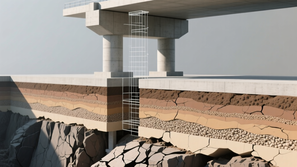
Geotechnical Decision Framework: SPT N-Values to Foundation Type
Selecting the optimal foundation system requires synthesizing the superstructure's load demands with the Standard Penetration Test (SPT) N-values derived from soil borings. The following framework guides structural engineers in matching soil density to foundation typology:
- N-Value < 5 (Very Soft Clay / Loose Silt): Shallow foundations are structurally unviable due to excessive consolidation settlement. Action: Specify deep foundations (friction piles) or implement deep soil mixing (DSM) to artificially improve the subgrade modulus.
- N-Value 10 to 30 (Medium Dense Sand / Stiff Clay): Ideal for shallow spread footings and strip footings for low-to-mid-rise structures (up to 5 stories). Action: Design isolated footings with standard flexural reinforcement, ensuring the footing depth satisfies ACI 318 one-way shear requirements without stirrups.
- N-Value 30 to 50 (Dense Sand / Hard Clay): Excellent bearing capacity (4,000+ psf). Suitable for mat foundations supporting high-rise cores or heavy industrial equipment. Action: Utilize a mat foundation to average out the high localized column loads and minimize differential settlement.
- N-Value > 50 or Refusal (Glacial Till / Bedrock): Near-incompressible strata. Action: If bedrock is shallow (< 15 ft), use shallow rock sockets. If deep, specify end-bearing steel H-piles or drilled shafts socketed directly into the rock to transfer massive axial loads with negligible settlement.
Ultimately, the structural analysis of foundation systems is an exercise in risk management. By rigorously evaluating soil mechanics, applying precise load combinations, and adhering to stringent material codes, engineers ensure that the chosen foundation type provides a permanent, stable anchor for the built environment.
Written by
Marcus ChenMarcus Chen is a licensed structural engineer (PE) and building materials analyst with over 12 years of experience across residential, commercial, and industrial construction. He holds a Master of Science in Civil Engineering from UC Berkeley and spent six years at Thornton Tomasetti before transitioning to independent consulting and technical writing. Marcus specializes in material selection for seismic-prone regions, concrete reinforcement strategies, and lifecycle cost analysis. His work has been cited by the American Concrete Institute (ACI) and the Structural Engineers Association of California (SEAOC). When he is not on a job site or at his desk, you will find him hiking the Sierra Nevada or restoring a 1920s craftsman bungalow in Oakland, CA.
More from Marcus Chen
View all
Construction Cost
How Much Did the Eiffel Tower Cost to Build?
How much did the Eiffel Tower cost to build in 1889? We adjust for inflation and compare its budget to modern skyscraper construction.
Aug 4, 2026
Fire Resistance
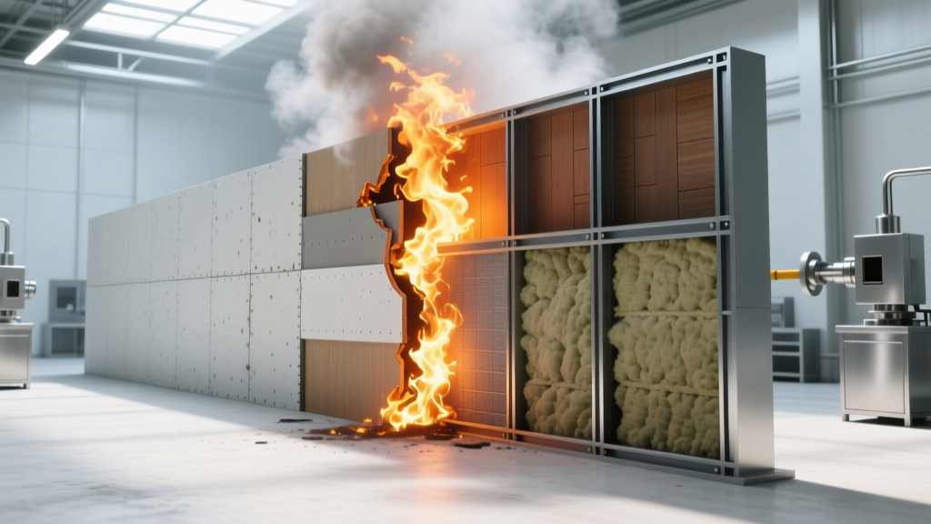
What Is a Fire Resistant Material? Testing & Certification Guide
Discover what is a fire resistant material through ASTM and UL testing. Learn how fire ratings, certifications, and assemblies work in construction.
Aug 4, 2026
Construction Cost
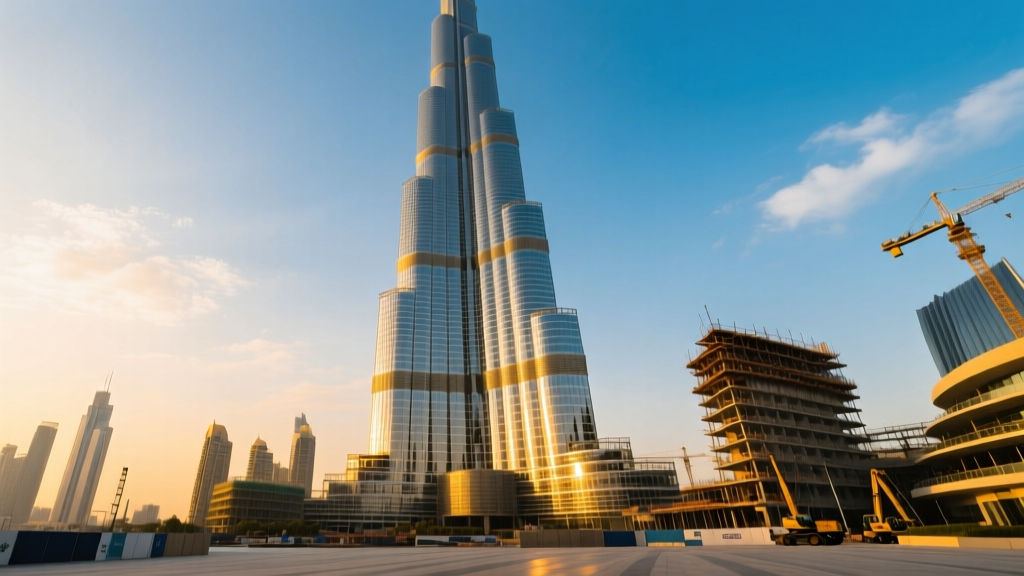
How Much Did the Burj Khalifa Cost to Build?
How much did the Burj Khalifa cost to build? We break down the $1.5B project and extract 5 money-saving strategies for your next build.
Jul 30, 2026