Types of House Foundation: A Structural Analysis of Load Transfer
A structural analysis of house foundation types, detailing load transfer mechanics, soil bearing capacities, and engineering retrofit solutions.
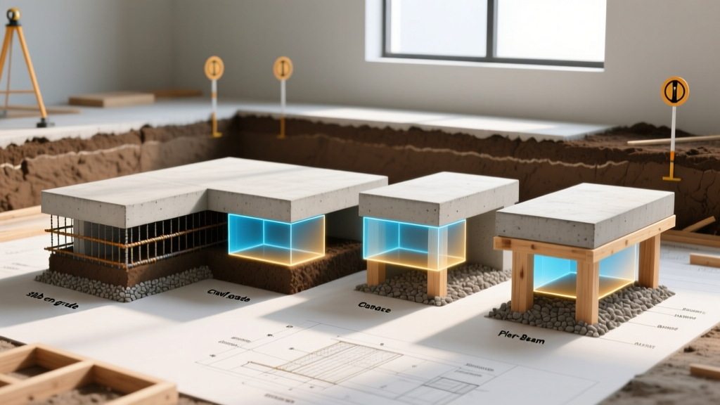
The Physics of Load Transfer and Soil Bearing Capacity
A foundation is fundamentally a load-transfer mechanism. Its primary structural objective is to distribute the cumulative dead loads (structural weight), live loads (occupants and furnishings), and environmental loads (wind, seismic, snow) into the underlying bearing strata without exceeding the soil's bearing capacity or inducing differential settlement. According to the International Building Code (IBC) Chapter 18, soil bearing capacity (SBC) dictates the footprint of footings. For instance, dense sand and gravel can support up to 4,000 pounds per square foot (psf), whereas soft clay may only safely support 1,000 psf. When the applied structural load exceeds the SBC, shear failure occurs in the soil mass, resulting in catastrophic structural collapse or severe differential settlement.
Structural engineers evaluate these forces using Rankine's earth pressure theory for lateral loads and Terzaghi's bearing capacity theory for vertical loads. The selection among the primary types of house foundation is not merely an architectural preference; it is a direct mathematical response to the geotechnical properties of the site and the specific load paths generated by the superstructure.
Structural Breakdown: Primary Foundation Systems Analyzed
Slab-on-Grade: Distributed Load Mechanics
Slab-on-grade foundations transfer loads uniformly across a continuous plane. In regions with expansive clay soils, conventional rebar-reinforced slabs often fail due to the immense uplift pressure generated by soil moisture fluctuations (swelling pressures can exceed 5,000 psf). To counteract this, structural engineers specify post-tensioned (PT) slabs. PT slabs utilize high-strength steel strands (typically 270 ksi yield strength) tensioned to 33,000 lbs after the concrete cures. This introduces a compressive pre-stress into the 4-inch to 5-inch concrete slab, effectively neutralizing tensile cracking caused by soil heave. The perimeter grade beams are typically sized at 12 inches wide by 24 inches deep, acting as stiffening ribs that bridge over localized soil voids.
Pier and Beam: Point Load Transfer
Pier and beam systems rely on point loads rather than distributed bearing. The structural integrity depends on the spacing of the piers (typically 8 to 10 feet on center) and the bending capacity of the primary girders (often 4x12 or 6x12 Douglas Fir or engineered LVL). Each pier transfers a concentrated load—often between 8,000 and 15,000 lbs depending on the tributary area—to an isolated concrete footing. The American Concrete Institute (ACI 332) mandates that these isolated footings must extend below the local frost line to prevent frost jacking, a phenomenon where freezing soil adheres to the pier and lifts it vertically, inducing severe shear stresses in the floor joists above.
Poured Concrete Basements: Retaining Wall Dynamics
A basement foundation functions simultaneously as a vertical load-bearing element and a cantilever retaining wall. The structural challenge is resisting lateral earth pressure and hydrostatic pressure from the surrounding soil. An 8-inch thick poured concrete wall with a compressive strength of 3,000 to 4,000 PSI, reinforced with #5 (5/8-inch) vertical rebar spaced at 24 inches on center, can typically resist the lateral loads of a standard 8-foot backfill. However, if the exterior drainage fails and the water table rises, hydrostatic pressure increases by 62.4 lbs per cubic foot of water depth. This exponential force easily exceeds the flexural capacity of the wall, leading to horizontal shear cracking and inward bowing.
Soil-Structure Interaction Matrix
The following matrix illustrates how geotechnical conditions dictate the structural modifications required for different foundation types.
| Soil Classification | Est. Bearing Capacity (psf) | Optimal Foundation Type | Required Structural Modification |
|---|---|---|---|
| Expansive Clay (CH) | 1,500 - 2,500 | Post-Tensioned Slab or Pier & Beam | Void forms (cartons) beneath grade beams; deep drilled piers to bedrock. |
| Loose Silty Sand (ML) | 2,000 - 3,000 | Continuous Strip Footing | Oversized footing widths (24"+); soil densification or vibro-compaction. |
| Organic Peat (Pt) | 0 - 1,000 | Deep Piling / Helical Piers | Bypass organic layer entirely; friction piles driven to 40+ feet depth. |
| Dense Glacial Till (GW) | 4,000 - 6,000 | Standard Slab or Basement | Minimal modification; standard 12"x6" footings typically sufficient. |
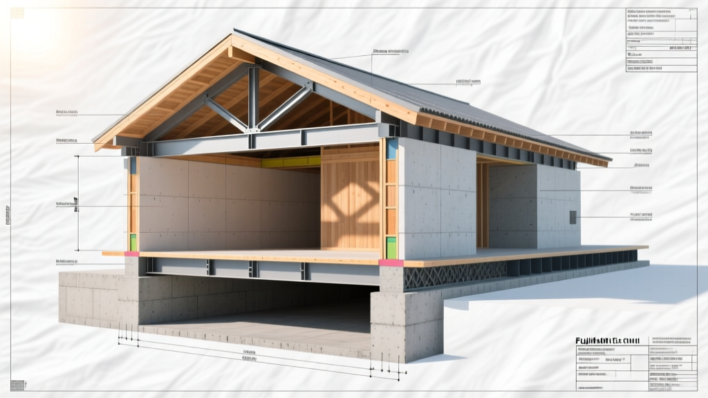
Failure Modes and Advanced Structural Retrofitting
When original foundation designs fail to account for actual site conditions or when environmental loads shift, structural retrofitting is required. The most common failure mode across all types of house foundation is differential settlement, where one section of the foundation sinks faster than another, inducing torsional stress on the rigid superstructure.
Diagonal drywall cracks emanating from door frames are often misdiagnosed as framing issues. Structurally, this indicates differential settlement exceeding the L/360 deflection limit of the foundation. Cosmetic patching will fail repeatedly until the underlying soil-structure interaction is stabilized.
Deep Foundation Underpinning
To arrest differential settlement, engineers utilize deep foundation underpinning to transfer the structural load from the failing shallow soils to a stable bearing stratum.
- Push Piers: Hydraulically driven through the unstable soil using the weight of the structure itself as reaction force. Ideal for heavy masonry or multi-story loads, requiring a minimum of 15,000 lbs of structural weight to drive the pier effectively.
- Helical Piers: Screwed into the ground using hydraulic torque motors. The structural capacity is directly correlated to the installation torque. For example, a 1.5-inch square shaft helical pier requiring 1,000 ft-lbs of torque to advance typically yields an ultimate axial capacity of approximately 20,000 lbs, based on the empirical torque-to-capacity factor (K-factor) of 10. FEMA's Building Science guidelines frequently recommend helical piers for lightweight wood-frame structures where push piers lack the necessary reaction mass for installation.
Lateral Stabilization of Basement Walls
For basement walls exhibiting inward deflection due to lateral earth pressure, structural engineers deploy carbon fiber reinforcement straps. These straps, possessing a tensile strength exceeding 100,000 PSI, are bonded to the concrete using structural epoxy. When anchored securely into the floor slab and the rim joist above, they create a composite structural section that increases the wall's flexural capacity by up to 40%, effectively halting further inward movement without the need for exterior excavation.
Geotechnical Decision Framework for Engineers
Selecting the appropriate foundation requires a systematic evaluation of the geotechnical report, typically performed under ASTM D1586 standards for soil sampling. Use the following decision framework during the schematic design phase:
- Evaluate the Plasticity Index (PI): If the soil PI exceeds 25, classify the site as highly expansive. Eliminate standard slab-on-grade from consideration; mandate drilled concrete piers extending a minimum of 5 feet below the active moisture zone.
- Assess the Water Table Elevation: If the seasonal high water table intersects the proposed basement depth, calculate the buoyancy force (62.4 lbs/cu ft). If the buoyant force exceeds the dead load of the empty structure, design a structural mat slab (raft foundation) to distribute the uplift pressure uniformly.
- Analyze Seismic Site Class: For sites classified as Site Class D (stiff soil) or E (soft clay) in high seismic zones, incorporate continuous load paths using epoxy-anchored hold-downs (e.g., Simpson Strong-Tie HDU series) tied directly from the top plate of the superstructure into the foundation stem wall to resist overturning moments.
Written by
David NakamuraDavid Nakamura is a licensed architect (AIA) and construction technology writer focused on sustainable building methods, mass timber engineering, and high-performance building envelopes. He holds a Master of Architecture from the University of Washington and is a certified Passive House Consultant (CPHC). David spent eight years at the Seattle firm Mithun, where he led the design of three LEED Platinum projects, before founding his own practice specializing in net-zero residential design. He serves on the editorial advisory board of GreenBuilder Magazine and has authored peer-reviewed papers on cross-laminated timber (CLT) connections for the Journal of Structural Engineering. In his spare time, David teaches woodworking at Pratt Fine Arts Center and kayaks the Puget Sound.
More from David Nakamura
View all
Construction Cost
Labor Cost to Build a Deck Per Sq Ft: 2026 Installation Guide
Discover the exact labor cost to build a deck per sq ft in 2026. This installation guide breaks down contractor rates, complexity factors, and hidden fees.
Aug 4, 2026
Construction Cost
How Much Does It Cost to Build a 3 Bedroom House? Financing Guide
Learn exactly how much it costs to build a 3 bedroom house and explore 2026 financing options, construction loan types, and budget frameworks for your build.
Aug 4, 2026
Construction Cost
Cost to Build a Tennis Court: 2026 Guide
How much does it cost to build a tennis court in 2026? Breakdowns for asphalt, concrete, and synthetic surfaces plus fencing and lighting.
Jul 30, 2026