Diagnosing Warning Signs Across All Types of Building Foundations
Learn to identify critical structural warning signs specific to your foundation type, from slab cracks to crawl space moisture and basement bowing.
The Mechanics of Foundation Failure: Why Type Dictates Diagnosis
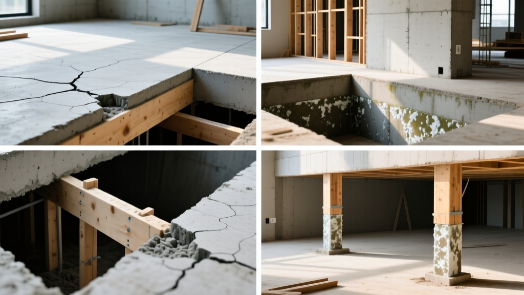
Foundation failures are rarely uniform. The structural behavior of a post-tensioned concrete slab differs vastly from a masonry basement wall under hydrostatic load. When diagnosing structural distress, applying a blanket approach leads to misdiagnosis and unnecessary repair costs. The specific types of building foundations react to soil movement, moisture fluctuations, and load stressors in entirely distinct ways. Accurate diagnosis requires understanding the unique failure modes, measurement thresholds, and material vulnerabilities inherent to your specific foundation system.
Quick-Reference Diagnostic Matrix
| Foundation Type | Primary Stressor | Critical Warning Sign | Action Threshold |
|---|---|---|---|
| Concrete Slab-on-Grade | Differential Settlement | Diagonal drywall cracks at door headers | Slope > 1 inch per 20 feet |
| Crawl Space | Moisture Intrusion / Wood Rot | Fungal growth on joists; musty odors | Wood Moisture Equivalent > 20% |
| Full Basement (CMU/Poured) | Lateral Earth / Hydrostatic Pressure | Horizontal cracking; inward wall bowing | Deflection > 2 inches |
| Pier and Beam | Point Load Punch-Through | Uneven floors; localized sagging | Beam deflection > L/360 ratio |
Concrete Slab-on-Grade: Settlement and Tension Failures
Slab foundations transfer the entire structural load directly to the underlying soil. The most common failure mode is differential settlement, where one section of the slab sinks faster than another due to varying soil moisture or poor compaction.
Diagnostic Metrics for Slabs
Do not panic at every hairline crack. Concrete cures and shrinks, leading to superficial map-cracking. True structural distress is measured by slope and specific crack geometries:
- Floor Slope Tolerance: According to standards derived from InterNACHI guidelines and ACI 117, a floor slope exceeding 1 inch over a 20-foot span warrants a structural evaluation.
- Crack Width: Vertical or diagonal cracks wider than 1/8 inch (approx. 3mm) that traverse the entire depth of the foundation edge indicate active shear stress.
- Door/Window Bind: If doors stick at the top corner rather than the latch side, the slab is likely experiencing a rotational drop.
Many modern slab foundations utilize post-tensioned steel cables. If you see a localized, explosive spalling of concrete on the slab edge or a rust-stained patch, a PT cable may have snapped or been accidentally cut during a plumbing repair. Never core-drill into a PT slab without first hiring a Ground Penetrating Radar (GPR) technician to map the cable grid.
Crawl Space Foundations: Moisture and Support Degradation
Crawl spaces elevate the wooden floor structure above the soil, creating a buffer zone. However, this buffer zone is highly susceptible to microclimate changes. The primary threat to a crawl space foundation is not the soil moving, but the wooden support structure decaying from trapped moisture.
Moisture Thresholds and Vapor Barriers
Diagnosing a crawl space requires a wood moisture meter. Fungal decay and dry rot organisms require a Wood Moisture Equivalent (WME) of at least 20% to activate and consume the cellulose in structural lumber.
- Acceptable WME: 8% to 14%.
- Warning Zone: 15% to 19% (indicates inadequate ventilation or vapor barrier failure).
- Critical Zone: 20%+ (active decay is highly probable; immediate encapsulation required).
Inspect the ground vapor barrier. While older building codes permitted 4-mil or 6-mil polyethylene sheeting, the 2026 industry standard for proper crawl space encapsulation requires a minimum 12-mil to 20-mil woven, cross-laminated polyethylene liner. If your existing barrier is brittle, torn, or thinner than a standard trash bag, soil moisture is actively evaporating into your floor joists.

Full Basement Foundations: Lateral Pressure and Hydrostatics
Basement foundations act as retaining walls. They must resist the lateral (sideways) pressure of the surrounding soil and the hydrostatic pressure of groundwater. Failure here is often catastrophic and progresses faster than slab settlement.
Reading Basement Wall Cracks
The material of your basement wall—Poured Concrete vs. Concrete Masonry Units (CMU / Cinder Block)—changes how the wall fails under pressure.
- CMU Block Walls: Look for stair-step cracking along the mortar joints. If the horizontal mortar joints begin to separate or slide (shear failure), the wall is actively yielding. According to University of Minnesota Extension, any inward deflection (bowing) exceeding 2 inches requires immediate stabilization via carbon fiber straps or steel I-beam bracing.
- Poured Concrete Walls: These walls typically fail via diagonal cracks originating at the corners of window cutouts or through mid-wall horizontal cracking. Watch for efflorescence (white, powdery mineral deposits). While efflorescence itself is harmless, it proves that water is actively migrating through the concrete matrix, carrying calcium hydroxide to the surface.
Pier and Beam Foundations: Point Loads and Shim Compression
Pier and beam systems distribute the home's weight across discrete concrete or masonry piers, which support heavy timber or engineered wood beams. Because the load is concentrated on specific points, the failure mode is usually localized 'punch-through' settlement or beam deflection.
Inspecting the Support Columns
When diagnosing pier and beam issues, access the crawlspace and inspect the connection between the concrete pier and the wooden beam above it.
- Shim Degradation: Builders use shims to level beams on piers. If wooden cedar shims are used, they can compress or rot over time. Modern best practices dictate the use of galvanized steel shims or high-density composite shims. If you can slide a putty knife easily between the pier cap and the beam, the shim has failed.
- Pier Plumbness: Use a 4-foot magnetic level on the side of the concrete piers. If a pier is leaning more than 1/4 inch over 4 feet, the soil beneath the pier's footing has shifted, and the pier must be underpinned or replaced.
- Beam Deflection: String a tight mason's line from one end of the main carrying beam to the other. Measure the gap between the string and the beam at the center. Deflection exceeding the L/360 ratio (e.g., 1 inch of sag for every 30 feet of span) indicates the beam is undersized or overloaded.
Professional Diagnostic Tools and 2026 Cost Expectations
While visual inspections and basic tools (like a 6-foot level and moisture meter) can identify obvious red flags, definitive diagnosis requires specialized equipment. If you observe multiple warning signs across your foundation type, hire a licensed Structural Engineer (PE) rather than a foundation repair contractor, to ensure an unbiased assessment.
Standard Diagnostic Equipment
- Digital Zip Levels / Water Levels: Used to map the exact topography and slope of a slab floor to an accuracy of 1/1000th of an inch.
- Ground Penetrating Radar (GPR): Essential for mapping rebar and post-tension cables before any intrusive testing or plumbing repairs are authorized.
- Thermal Imaging (Infrared): Used to detect hidden moisture intrusion behind finished basement walls or missing insulation in crawl spaces that may be causing localized frost heave.
As of 2026, expect to pay between $650 and $1,100 for a comprehensive, independent structural engineer's diagnostic report, which should include floor elevation mapping, soil plasticity analysis, and a stamped repair prescription. Foundation repair contractors often offer 'free' inspections, but their diagnostics are inherently tied to selling their specific proprietary repair systems (e.g., pushing piers vs. helical piers).
Next Steps for Homeowners
Document all cracks with dated photographs and a reference object (like a coin) for scale. Monitor them over a 30-day period using inexpensive glass crack monitors or digital calipers. If a crack widens by more than 1/16 inch in a single month, the settlement is active, and immediate professional intervention is required to prevent secondary damage to your roof trusses and plumbing lines.
Written by
David NakamuraDavid Nakamura is a licensed architect (AIA) and construction technology writer focused on sustainable building methods, mass timber engineering, and high-performance building envelopes. He holds a Master of Architecture from the University of Washington and is a certified Passive House Consultant (CPHC). David spent eight years at the Seattle firm Mithun, where he led the design of three LEED Platinum projects, before founding his own practice specializing in net-zero residential design. He serves on the editorial advisory board of GreenBuilder Magazine and has authored peer-reviewed papers on cross-laminated timber (CLT) connections for the Journal of Structural Engineering. In his spare time, David teaches woodworking at Pratt Fine Arts Center and kayaks the Puget Sound.
More from David Nakamura
View all
Construction Cost
Labor Cost to Build a Deck Per Sq Ft: 2026 Installation Guide
Discover the exact labor cost to build a deck per sq ft in 2026. This installation guide breaks down contractor rates, complexity factors, and hidden fees.
Aug 4, 2026
Construction Cost
How Much Does It Cost to Build a 3 Bedroom House? Financing Guide
Learn exactly how much it costs to build a 3 bedroom house and explore 2026 financing options, construction loan types, and budget frameworks for your build.
Aug 4, 2026
Construction Cost
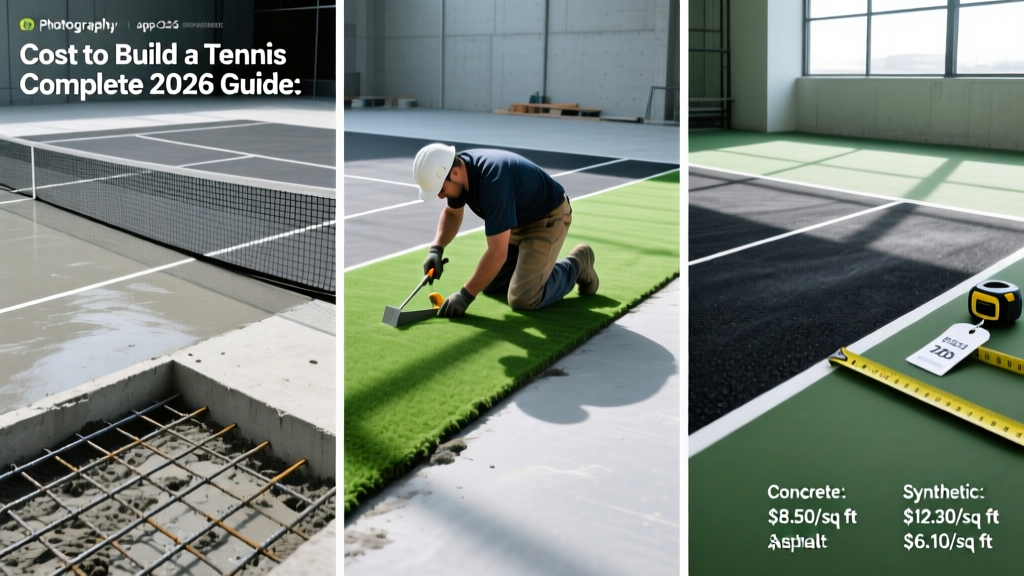
Cost to Build a Tennis Court: 2026 Guide
How much does it cost to build a tennis court in 2026? Breakdowns for asphalt, concrete, and synthetic surfaces plus fencing and lighting.
Jul 30, 2026