Proper Car Insulation Material Installation for Acoustic Control
Learn exact installation techniques for butyl, CCF, and MLV car insulation material. Master surface prep, coverage ratios, and rolling for a quiet cabin.

The Physics of Vehicle Noise and Thermal Transfer
Automotive sheet metal typically ranges from 0.8mm to 1.2mm in thickness. At this gauge, steel acts as an acoustic diaphragm, efficiently transmitting low-frequency structure-borne noise (road hum, exhaust drone) into the cabin while offering virtually no thermal resistance. Effective acoustic and thermal treatment requires a multi-stage approach that targets both structure-borne vibration and airborne noise. Applying a single layer of adhesive-backed foam is a fundamentally flawed approach that fails to address the distinct physics of resonant frequencies and airborne sound transmission.
To achieve a 10dB to 15dB reduction in cabin noise and stabilize interior temperatures, installers must utilize a three-layer system: Constrained Layer Dampers (CLD), Closed-Cell Foam (CCF) decouplers, and Mass Loaded Vinyl (MLV) sound blockers. According to the Institute of Noise Control Engineering, treating the source of vibration before blocking the airborne path is the only scientifically valid method for automotive acoustic isolation.
Material Selection: The Three-Layer System
Layer 1: Butyl Rubber Constrained Layer Dampers (CLD)
CLD mats consist of a viscoelastic butyl rubber base bonded to a rigid aluminum constraint layer. When the metal panel vibrates, the butyl layer undergoes shear deformation, converting kinetic energy into negligible amounts of heat.
Layer 2: Closed-Cell Foam (CCF) Decouplers
CCF serves two purposes: thermal insulation and mechanical decoupling. A 1/8-inch to 1/4-inch layer of CCF prevents the heavy MLV layer from directly contacting the metal chassis, which would otherwise create a secondary rattle point and short-circuit the mass-blocking effect. CCF must be strictly closed-cell; open-cell foams absorb condensation, leading to hidden floor pan rust and mold growth.
Layer 3: Mass Loaded Vinyl (MLV) Sound Blockers
MLV is a limp-mass barrier loaded with barium salts or calcium silicate to achieve high density without structural rigidity. The Mass Law of acoustics dictates that doubling the mass of a barrier yields a 6dB reduction in airborne noise transmission. Standard automotive MLV weighs 1 lb per square foot, providing the necessary density to block high-frequency tire whine and exhaust hiss.
Pre-Installation: Surface Preparation Protocol
Adhesion failure is the primary cause of CLD delamination. The factory metal must be stripped to bare steel or factory E-coat and chemically degreased.
- Strip Factory Mastic: Use a heat gun set to 200°F and a plastic scraper to remove factory spot-weld sealants and tar patches. Do not use metal scrapers, which will gouge the E-coat and initiate corrosion.
- Chemical Degrease: Wipe all target surfaces with 70% or higher isopropyl alcohol (IPA) or a dedicated automotive wax and grease remover. Use lint-free microfiber towels, changing them frequently to avoid smearing dissolved oils back onto the panel.
- Masking: Use 3M automotive masking tape to protect wiring harness connectors, seat track threads, and latch mechanisms from butyl residue and adhesive overspray.
Step-by-Step Installation Techniques
Phase 1: Applying the CLD (Butyl) Layer
The most common amateur mistake is attempting 100% coverage with butyl CLD. This adds unnecessary weight and yields diminishing returns. Technical documentation from Dynamat's engineering team confirms that covering just 25% to 35% of a flat panel's surface area is sufficient to shift the panel's resonant frequency below the audible threshold.
- Score and Snap: Cut the butyl mat with a sharp utility knife using a metal straightedge. Score through the butyl, then bend the mat backward to snap the aluminum constraint layer cleanly.
- Position and Tack: Peel back 2 inches of the release liner. Position the mat on the panel and press the exposed edge to anchor it, preventing the mat from shifting during the rolling process.
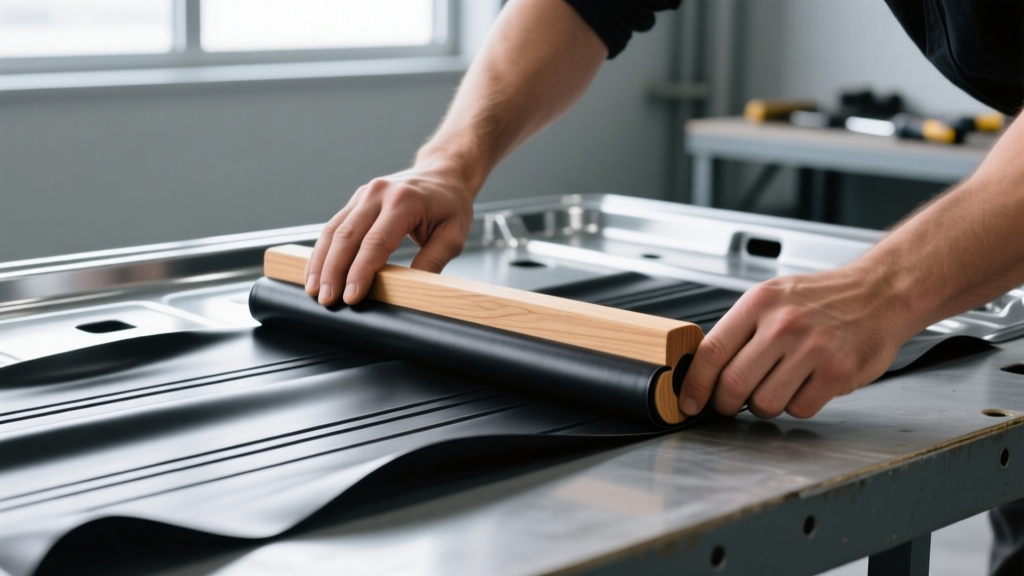
- Activate the Adhesive: Using a hard wooden or metal-core seam roller, apply a minimum of 15 lbs of downward pressure. Roll in overlapping, cross-hatched passes (horizontal, then vertical). The aluminum layer must be pressed so firmly that the texture of the underlying metal is slightly visible through the foil. If the foil is smooth and untextured, the butyl has not made full contact.
Phase 2: Laying the CCF and MLV Layers
Unlike the butyl layer, CCF and MLV require near 100% coverage to be effective, as they block airborne noise and thermal transfer.
- Template Creation: Use heavy craft paper or painter's plastic to create exact templates of the floor pans, transmission tunnel, and firewall. Transfer these templates to the CCF and MLV sheets.
- Adhesive Application: Spray a high-tack, high-temperature contact adhesive (e.g., 3M Super 77 or 3M 90) onto both the vehicle metal and the back of the CCF. Wait 3 to 5 minutes for the solvents to flash off until the adhesive feels tacky but does not transfer to your knuckle.
- Layering: Press the CCF into place. Next, apply contact adhesive to the top of the CCF and the back of the MLV. Lay the MLV over the CCF, ensuring the edges overlap slightly at the seams to prevent acoustic flanking (noise leaking through microscopic gaps).
- Seam Sealing: Seal all MLV seams and perimeter edges with 2-inch acoustic aluminum tape to create a continuous, airtight barrier.
Common Installation Failures and Edge Cases
Even with premium materials, poor execution in high-risk areas will compromise the entire system. Review this decision matrix to avoid critical failures.
| Failure Symptom | Root Cause | Corrective Action |
|---|---|---|
| Interior water accumulation / rusted floor pans | MLV or butyl applied over door cavity drain holes or floor pan plugs. | Cut precise 1/2-inch relief holes in all insulation layers directly over factory weep holes. Never seal the bottom edge of a door cavity. |
| Electrical shorts or blown fuses post-installation | Wiring harnesses trapped directly beneath heavy MLV without a buffer. | Route all wiring harnesses on top of the MLV, or cut dedicated channels into the CCF layer to cradle the wires. MLV friction will wear through wire loom insulation over time. |
| Cross-threaded seat bolts during reassembly | Butyl residue pushed into seat track threaded inserts during rolling. | Mask threaded inserts before applying butyl. If contaminated, run an M8 or M10 thread chaser (not a standard tap) through the insert to clear the viscoelastic rubber. |
| Buzzing or rattling at high audio volumes | Speaker wires or plastic trim clips vibrating against the aluminum CLD layer. | Apply a 1-inch strip of CCF or acoustic foam tape over any sharp edges, wire runs, or clip insertion points that contact the CLD foil. |
Zonal Treatment Strategies
Different vehicle zones require distinct material configurations based on spatial constraints and noise sources. Industry guides, such as those published by automotive acoustic specialists, recommend the following zonal breakdowns:
- Doors: Apply butyl CLD to the outer door skin (behind the speaker) and the inner access panel. Use CCF on the door card (interior trim panel) to prevent plastic-on-metal rattles. Avoid MLV in doors; the added 20+ lbs per door will overstress factory hinges and window regulators.
- Floor Pan & Firewall: Full three-layer treatment (CLD, CCF, MLV). The firewall is the primary entry point for engine and exhaust drone. Ensure MLV extends at least 4 inches up the firewall beneath the dashboard.
- Roof: Apply butyl CLD strips to the center of the roof panel to eliminate rain drumming and structural resonance. Do not apply CCF or MLV to the roof; the added weight raises the vehicle's center of gravity, and the thickness will prevent the headliner from clipping back into place.
- Trunk / Hatch: Treat the spare tire well and rear wheel arches heavily with CLD and CCF. These large, unsupported cavities act as acoustic amplifiers for rear tire noise and exhaust muffler resonance.
Cost and Material Yield Estimates (2026 Pricing)
Budgeting for a comprehensive acoustic and thermal overhaul requires accounting for material yield, waste factors, and specialized tooling. The table below outlines expected costs for a standard mid-size sedan (e.g., Honda Accord, Toyota Camry) requiring approximately 50 square feet of floor/door coverage.
| Material Type | Average Cost (per sq. ft.) | Estimated Yield (Mid-Size Sedan) | Total Estimated Cost |
|---|---|---|---|
| Butyl CLD (2mm + 100µm foil) | $1.80 - $3.20 | 15 - 20 sq. ft. (25% coverage) | $27 - $64 |
| Closed-Cell Foam (1/4') | $0.90 - $1.50 | 45 - 50 sq. ft. | $40 - $75 |
| Mass Loaded Vinyl (1 lb/sq ft) | $2.50 - $4.00 | 45 - 50 sq. ft. | $112 - $200 |
| Consumables (Adhesive, Tape, IPA) | N/A | 1 Kit | $45 - $80 |
| Total Project Cost | $224 - $419 |
Professional installation labor typically adds $600 to $1,200 to this total, as the process requires complete removal of the interior seating, center console, dashboard lower trim, and carpeting. For DIY installers, investing in a $25 hard wooden seam roller and a $40 trim removal tool kit will prevent costly damage to fragile interior plastic clips during the teardown phase.
Written by
Marcus ChenMarcus Chen is a licensed structural engineer (PE) and building materials analyst with over 12 years of experience across residential, commercial, and industrial construction. He holds a Master of Science in Civil Engineering from UC Berkeley and spent six years at Thornton Tomasetti before transitioning to independent consulting and technical writing. Marcus specializes in material selection for seismic-prone regions, concrete reinforcement strategies, and lifecycle cost analysis. His work has been cited by the American Concrete Institute (ACI) and the Structural Engineers Association of California (SEAOC). When he is not on a job site or at his desk, you will find him hiking the Sierra Nevada or restoring a 1920s craftsman bungalow in Oakland, CA.
More from Marcus Chen
View all
Construction Cost
How Much Did the Eiffel Tower Cost to Build?
How much did the Eiffel Tower cost to build in 1889? We adjust for inflation and compare its budget to modern skyscraper construction.
Aug 4, 2026
Fire Resistance
What Is a Fire Resistant Material? Testing & Certification Guide
Discover what is a fire resistant material through ASTM and UL testing. Learn how fire ratings, certifications, and assemblies work in construction.
Aug 4, 2026

Construction Cost
How Much Did the Burj Khalifa Cost to Build?
How much did the Burj Khalifa cost to build? We break down the $1.5B project and extract 5 money-saving strategies for your next build.
Jul 30, 2026