Modern Stone Veneer Fireplace Technical Specs & Clearances
Detailed technical specifications for modern stone veneer fireplaces, covering load deflection, NFPA 211 clearances, mortar types, and substrate prep.

Core Structural Parameters & Load Deflection Limits
Engineering a modern stone veneer fireplace requires strict adherence to structural deflection limits. Unlike flexible cladding materials, masonry veneer possesses near-zero tensile strength. When the underlying framing bends under live, dead, or wind loads, the rigid mortar matrix fractures, leading to catastrophic delamination. For natural thin stone veneer (NTSV), the International Building Code (IBC) and industry standards mandate a maximum deflection limit of L/600. For manufactured stone masonry veneer (MSMV), the limit is slightly more forgiving at L/360, though high-end custom installations should default to L/600 regardless of material origin.
Standard 2x4 wood framing at 16 inches on-center (o.c.) often fails to meet the L/600 deflection requirement for heavy natural stone surrounds exceeding 8 feet in height. Upgrade to 2x6 framing, reduce spacing to 12 inches o.c., or utilize 20-gauge (minimum) steel studs with heavy-duty track to achieve the required rigidity.
Substrate Preparation & Moisture Management
The substrate is the primary failure point in 78% of interior and exterior veneer fireplace callbacks. Gypsum-based drywall or green board is strictly prohibited as a backing material for any masonry veneer, regardless of whether the fireplace is wood-burning or gas. The thermal cycling of a fireplace rapidly degrades paper-faced gypsum, destroying its shear capacity.
Approved Substrate Matrix
- Interior Non-Combustible Zones: 1/2-inch or 5/8-inch Portland cement-based backer board (e.g., Durock, HardieBacker) or fiber-cement board, rated for continuous exposure to 200°F+.
- Interior Standard Zones (Outside clearance zones): 1/2-inch cement board over 15 lb asphalt felt or a liquid-applied waterproofing membrane.
- Exterior Chimney Chases: 1/2-inch exterior-grade gypsum sheathing (glass-mat faced, ASTM C1177) or exterior cement board, covered by a Water Resistive Barrier (WRB).
Water Resistive Barrier (WRB) & Flashing Specs
For exterior fireplace chases or interior installations where moisture migration is a concern, a dual-layer WRB system is required. The first layer acts as a bond-breaker, while the second provides the primary water resistance. Install a corrosion-resistant weep screed at the base of the veneer with a minimum 1-inch clearance from the hearth or finished floor. Integrate the weep screed with the WRB using cap nails spaced 6 inches o.c., ensuring all water is directed outward, away from the structural framing.
Mortar Chemistry & Adhesive Specifications
Selecting the correct bonding agent is dictated by the veneer type and the thermal profile of the fireplace. Standard latex additives break down when exposed to the sustained high temperatures radiating from a firebox surround. Therefore, polymer-modified thin-sets are restricted to the outer, non-combustible clearance zones of gas or electric fireplaces.
| Veneer Category | Weight (psf) | Scratch Coat Spec | Setting Mortar Requirement |
|---|---|---|---|
| Natural Thin Veneer | 10 - 15 | 3/8' to 1/2' Type S | Type S Mortar (ASTM C270) |
| Manufactured Stone (MSMV) | 7 - 12 | 3/8' to 1/2' Type N or S | Type N or S Mortar, or ANSI A118.4 Thinset (Low-heat zones) |
| Panelized Polyurethane/Stone | 1 - 3 | None Required | Construction Adhesive (ASTM C557) + Mechanical Fasteners |
For high-heat zones immediately surrounding the firebox opening, utilize a Type S mortar mixed with a Portland cement base (ASTM C150 Type II). Type II cement is specifically formulated with lower tricalcium aluminate (C3A) content, which drastically reduces the risk of sulfate attack and efflorescence—a common aesthetic failure where white, powdery salt deposits bloom on the stone surface due to heat-accelerated moisture migration.
Thermal Clearances & NFPA 211 Compliance
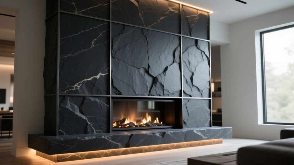
The intersection of combustible framing, masonry veneer, and high-heat appliances is governed by NFPA 211: Standard for Chimneys, Fireplaces, Vents, and Solid Fuel-Burning Appliances. When constructing a modern stone veneer fireplace around a zero-clearance insert or a traditional masonry firebox, thermal expansion and combustibility clearances are non-negotiable.
"Masonry expands when heated. A stone veneer surround tied rigidly to a steel firebox insert without an expansion joint will transfer thermal stress directly to the veneer, resulting in vertical shear cracking within the first three heating cycles."
Clearance Mapping & Expansion Joints
- Combustible Mantel Clearances: Maintain a minimum 12-inch vertical clearance from the top of the firebox opening to any combustible wood mantel. For every 1/8-inch the mantel protrudes beyond the face of the stone veneer, add 1 inch of vertical clearance.
- Non-Combustible Air Space: When veneering over a masonry firebox, maintain a 2-inch air space between the firebox exterior and any combustible framing behind the cement board. Fill this cavity with non-combustible mineral wool insulation (e.g., Rockwool Safe'n'Sound) to prevent convective heat loops.
- Hearth Expansion Joint: Do not mortar the bottom course of stone veneer directly to the concrete or tile hearth. Leave a 1/4-inch gap and seal it with a high-temperature, non-combustible silicone sealant meeting ASTM C920 Grade NS, Class 25. This isolates the vertical veneer load from the horizontal hearth slab, accommodating differential thermal expansion.
Anchoring, Lath, and Fastener Specifications
Mechanical keying is mandatory for all cementitious stone veneer applications exceeding 10 square feet. The lath system transfers the dead load of the stone and mortar directly into the structural framing, bypassing the sheer strength limitations of the cement board.
- Lath Material: Use only self-furring, galvanized diamond mesh lath weighing a minimum of 2.5 lbs per square yard (ASTM C847). Do not use paper-backed lath or lightweight stucco netting.
- Orientation: Install the lath horizontally. The self-furring dimples must face outward, away from the substrate, to allow the scratch coat mortar to wrap behind the wire mesh, creating a mechanical lock.
- Fastening Schedule: Secure the lath using 1.5-inch galvanized roofing nails (for wood studs) or self-drilling TEK screws with ribbed washer heads (for steel studs). Fasteners must penetrate the structural framing by a minimum of 3/4-inch. Space fasteners at 6 inches o.c. vertically and 16 inches o.c. horizontally. Overlap all lath seams by a minimum of 1 inch horizontally and 2 inches vertically.
Diagnostic Guide: Common Failure Modes
Even with premium materials, modern stone veneer fireplaces fail when environmental variables are ignored. Below is a diagnostic framework for the three most prevalent technical failures.
1. Substrate Delamination (The 'Hollow' Sound)
Symptom: Tapping the veneer yields a hollow acoustic response; stones detach under light pressure.
Root Cause: Failure to dampen the scratch coat before applying the setting bed, or applying mortar to a dusty, unprimed cement board surface. The mortar cured too rapidly, preventing crystalline hydration.
Technical Fix: Pre-wet the scratch coat until it reaches a saturated-surface-dry (SSD) state. Apply a bonding agent (ASTM C1384) to the back of low-porosity natural stones prior to setting.
2. Severe Efflorescence Blooming
Symptom: White, crystalline powder accumulates on the mortar joints and stone faces, particularly near the firebox.
Root Cause: Use of high-alkali masonry sand or unwashed beach sand in the mortar mix, combined with heat-driven moisture migration from the interior wall cavity.
Technical Fix: Specify ASTM C144 washed masonry sand. Apply a penetrating, breathable siloxane-based sealer (ASTM E96 compliant) to the stone face only, avoiding the mortar joints to allow vapor egress.
3. Vertical Shear Cracking at Corners
Symptom: Hairline cracks propagate vertically from the outer corners of the firebox opening up to the ceiling.
Root Cause: Concentrated thermal stress at the geometric discontinuity of the firebox corner, compounded by a lack of continuous lath wrapping.
Technical Fix: When installing lath, ensure it wraps continuously around outside and inside corners by a minimum of 8 inches in both directions. Never terminate a lath seam directly on a corner. For high-heat gas inserts, embed a 4-inch wide fiberglass mesh tape (alkali-resistant) in the scratch coat at all firebox corners.
Authoritative References & Standards
Compliance with current building codes and material standards is mandatory for liability and structural integrity. The technical parameters outlined in this guide are synthesized from the following authoritative frameworks:
- NFPA 211: Standard for Chimneys, Fireplaces, Vents, and Solid Fuel-Burning Appliances - Governs thermal clearances and combustible isolation.
- ASTM C1670: Standard Specification for Manufactured Stone Masonry Veneer - Dictates compressive strength, absorption rates, and freeze-thaw durability for MSMV products.
- NVMA Installation Guide: The National Veneer Stone Association provides the definitive industry-accepted protocols for lath, scratch coat, and mortar application sequences.
Written by
David NakamuraDavid Nakamura is a licensed architect (AIA) and construction technology writer focused on sustainable building methods, mass timber engineering, and high-performance building envelopes. He holds a Master of Architecture from the University of Washington and is a certified Passive House Consultant (CPHC). David spent eight years at the Seattle firm Mithun, where he led the design of three LEED Platinum projects, before founding his own practice specializing in net-zero residential design. He serves on the editorial advisory board of GreenBuilder Magazine and has authored peer-reviewed papers on cross-laminated timber (CLT) connections for the Journal of Structural Engineering. In his spare time, David teaches woodworking at Pratt Fine Arts Center and kayaks the Puget Sound.
More from David Nakamura
View all
Construction Cost
Labor Cost to Build a Deck Per Sq Ft: 2026 Installation Guide
Discover the exact labor cost to build a deck per sq ft in 2026. This installation guide breaks down contractor rates, complexity factors, and hidden fees.
Aug 4, 2026
Construction Cost
How Much Does It Cost to Build a 3 Bedroom House? Financing Guide
Learn exactly how much it costs to build a 3 bedroom house and explore 2026 financing options, construction loan types, and budget frameworks for your build.
Aug 4, 2026
Construction Cost
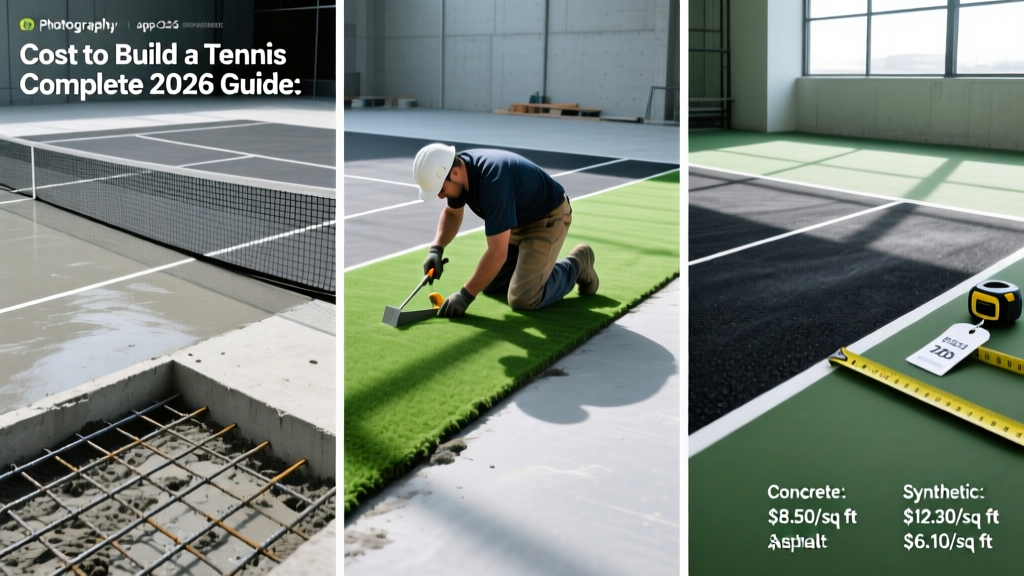
Cost to Build a Tennis Court: 2026 Guide
How much does it cost to build a tennis court in 2026? Breakdowns for asphalt, concrete, and synthetic surfaces plus fencing and lighting.
Jul 30, 2026