Natural Thin Stone Veneer Technical Specs & Weight Limits
Master natural thin stone veneer technical specs, including weight limits, substrate deflection, mortar standards, and moisture management details.

Dimensional and Weight Specifications
The term "thin" in natural thin stone veneer (NTSV) refers strictly to the cross-sectional profile, not the material density. Unlike manufactured concrete veneer, which incorporates lightweight aggregates, NTSV is sliced directly from full-bed natural quarried stone. This results in significant weight variations depending on the geological composition of the stone.
| Material Property | Natural Thin Stone Veneer | Full Bed Natural Stone | Manufactured Stone Veneer |
|---|---|---|---|
| Nominal Thickness | 0.75" to 1.5" | 3.0" to 5.0" | 0.5" to 1.25" |
| Weight (Granite/Basalt) | 14 - 18 lbs / sq ft | 38 - 48 lbs / sq ft | 10 - 12 lbs / sq ft |
| Weight (Limestone/Sandstone) | 11 - 14 lbs / sq ft | 30 - 38 lbs / sq ft | 9 - 11 lbs / sq ft |
| Weight (Slate) | 13 - 16 lbs / sq ft | 35 - 42 lbs / sq ft | N/A |
When calculating structural loads, engineers must use the upper bound of the specific stone type's weight range, plus an additional 1.5 to 2.0 lbs per square foot to account for the scratch coat, setting bed, and mortar joints. According to the Natural Stone Institute Technical Bulletins, failing to account for the mortar mass is a common miscalculation that leads to undersized structural supports.
Substrate and Structural Load Requirements
Because NTSV is an adhered veneer, it relies entirely on the substrate for structural support. The framing must resist both the gravity loads (dead weight) and lateral loads (wind/seismic) without excessive deflection.
Deflection Limits
The maximum allowable deflection for any substrate supporting adhered natural stone veneer is L/360 under total load. If a wall assembly deflects beyond this threshold under wind pressure or structural settling, the rigid mortar matrix will crack, leading to delamination. For steel stud framing, this typically mandates a minimum 20-gauge stud thickness at 16 inches on center (o.c.) for exterior walls exceeding 10 feet in height.
Wood vs. Steel Framing Specs
- Wood Framing: Minimum 2x4 studs at 16" o.c. (24" o.c. is permissible only if engineered sheathing and specific lath schedules are approved by the local building official). Maximum wall height without intermediate shelf angles is typically 12 feet.
- Steel Stud Framing: Minimum 20-gauge (0.033" thick) steel studs at 16" o.c. For commercial applications exceeding 30 feet, 16-gauge or 18-gauge studs are required, often supplemented with horizontal bracing channels.
- Concrete/CMU: Requires no structural lath if the surface is properly scarified and clean, but a scratch coat is still mandatory to ensure a uniform bonding surface.
Moisture Management and Flashing Specifications
Moisture intrusion is the primary cause of NTSV system failure. The assembly must be designed as a drained and vented rainscreen or a face-sealed mass wall with a secondary drainage plane. The International Building Code (IBC) Chapter 14 mandates specific weather-resistive barrier (WRB) configurations for adhered masonry veneer.
Required Moisture Assembly Layers (Exterior)
- Sheathing: OSB, plywood, or exterior-grade gypsum board.
- Primary WRB: House wrap or fluid-applied membrane.
- Secondary WRB: Grade D building paper (ASTM D226) or a dimpled drainage mat. This sacrificial layer protects the primary WRB from the alkaline mortar.
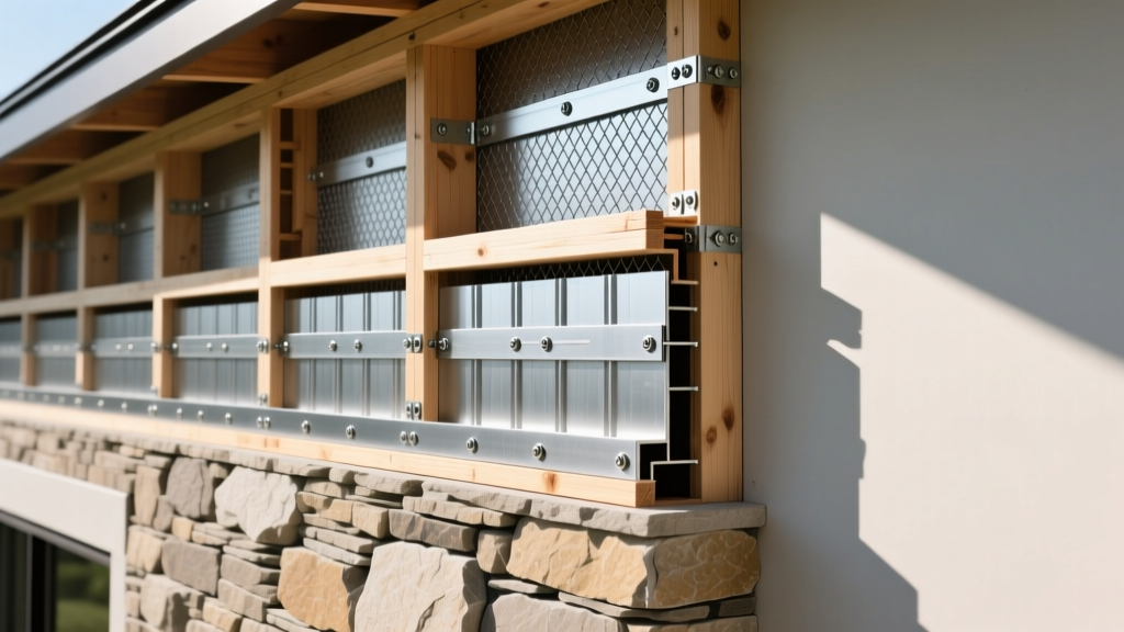
- Corrosion-Resistant Lath: Minimum 2.5 lb/sq yd self-furring galvanized steel lath (ASTM C847). Must be fastened with corrosion-resistant nails or screws penetrating the studs by at least 1 inch.
- Weep Screed: Minimum 0.019-inch thick galvanized or PVC weep screed (ASTM C1063) installed at the base of all walls.
Clearance Requirements: The weep screed must be installed a minimum of 4 inches above finished earth grade, or 2 inches above paved surfaces, decks, and concrete steps. This prevents capillary action and ground moisture from wicking into the stone assembly.
Mortar, Scratch Coat, and Adhesive Standards
The bond between the stone and the substrate is governed by the mortar specification. For exterior applications, polymer-modified thin-set adhesives used in tile setting are generally prohibited unless explicitly tested and certified by the stone manufacturer for exterior freeze-thaw conditions.
Mortar Specifications
Exterior NTSV installations require Type S Mortar conforming to ASTM C270. Type S provides a higher tensile bond strength (minimum 180 psi) compared to Type N (minimum 75 psi), which is critical for supporting the heavy dead load of natural stone on vertical surfaces. The mortar mix ratio is typically 1 part Portland cement, 0.5 parts hydrated lime, and 4.5 parts damp masonry sand.
Application Thickness and Sequence
- Scratch Coat: Apply a 3/8" to 1/2" thick layer of Type S mortar over the metal lath. Horizontally comb the scratch coat with a notched trowel to create mechanical keyways. Crucial: Allow the scratch coat to cure for a minimum of 24 to 48 hours before applying the stone.
- Setting Bed: Apply a 1/2" to 3/4" layer of fresh mortar to the back of each stone piece (back-buttering) and a 1/2" layer to the scratch coat. Press the stone firmly until mortar squeezes out on all sides.
- Jointing: Mortar joints should be 3/8" to 1/2" wide and struck with a concave jointer to compress the mortar against the stone edges, creating a water-shedding profile.
Expansion and Control Joint Specifications
Natural stone and the cementitious mortar matrix expand and contract at different rates due to thermal fluctuations and moisture absorption. The TMS 402 Building Code Requirements for Masonry Structures dictate the placement of control joints to prevent uncontrolled cracking.
• Horizontal Spacing: Maximum 20 to 25 feet apart.
• Vertical Spacing: Maximum 12 feet apart (typically aligned with floor lines in multi-story construction).
• Aspect Ratio: The area of veneer between control joints should not exceed 200 square feet, and the ratio of length to height should not exceed 3:1.
Control joints must be continuous and align exactly with the control joints in the underlying structural substrate. They should be filled with a high-quality, non-staining polyurethane or silicone sealant (ASTM C920) with a closed-cell backer rod, allowing for lateral movement without compromising the weather seal.
Freeze-Thaw Durability and Absorption Limits
Not all natural stones perform equally in freezing climates. The technical specification that dictates freeze-thaw survivability is the stone's water absorption rate, tested per ASTM C97. When water trapped in the stone's pores freezes, it expands by 9%, creating internal spalling pressures.
- Granite and Quartzite: Absorption rate typically < 0.5%. Highly resistant to freeze-thaw damage. Ideal for harsh northern climates.
- Limestone and Marble: Absorption rate ranges from 1% to 6%. Requires proper detailing, overhangs, and potentially penetrating siloxane sealers to prevent saturation.
- Sandstone: Absorption rate can exceed 6%. Highly susceptible to spalling and delamination in freeze-thaw zones unless specifically quarried from high-density, low-porosity deposits. Avoid using high-absorption sandstone on north-facing elevations where ice dams and prolonged moisture exposure occur.
For any NTSV product installed in a climate with more than 15 freeze-thaw cycles annually, the manufacturer must provide test data demonstrating compliance with ASTM C666 (Standard Test Method for Resistance of Concrete to Rapid Freezing and Thawing) or equivalent natural stone durability testing, showing less than 1% weight loss and no structural degradation after 300 cycles.
Written by
David NakamuraDavid Nakamura is a licensed architect (AIA) and construction technology writer focused on sustainable building methods, mass timber engineering, and high-performance building envelopes. He holds a Master of Architecture from the University of Washington and is a certified Passive House Consultant (CPHC). David spent eight years at the Seattle firm Mithun, where he led the design of three LEED Platinum projects, before founding his own practice specializing in net-zero residential design. He serves on the editorial advisory board of GreenBuilder Magazine and has authored peer-reviewed papers on cross-laminated timber (CLT) connections for the Journal of Structural Engineering. In his spare time, David teaches woodworking at Pratt Fine Arts Center and kayaks the Puget Sound.
More from David Nakamura
View all
Construction Cost
Labor Cost to Build a Deck Per Sq Ft: 2026 Installation Guide
Discover the exact labor cost to build a deck per sq ft in 2026. This installation guide breaks down contractor rates, complexity factors, and hidden fees.
Aug 4, 2026
Construction Cost
How Much Does It Cost to Build a 3 Bedroom House? Financing Guide
Learn exactly how much it costs to build a 3 bedroom house and explore 2026 financing options, construction loan types, and budget frameworks for your build.
Aug 4, 2026
Construction Cost
Cost to Build a Tennis Court: 2026 Guide
How much does it cost to build a tennis court in 2026? Breakdowns for asphalt, concrete, and synthetic surfaces plus fencing and lighting.
Jul 30, 2026